

3D Design — exact parts from a few numbers or plain words
Design the part in the design workbench as a feature tree, change the numbers of a ready design or describe the part to Cowork, and get an exact STEP solid; the 3D kernel checks it, the viewer opens it, one click makes it a product.
- Parametric workbenchA feature tree, parameters as formulas, undo, and a solid rebuilt after every change.
- No code to writePick a ready design and change its numbers in the form.
- In plain wordsCowork turns the part into code from what PORTWARE knows and builds it.
- An exact solidThe result is a STEP solid every CAD program opens, not a mesh.
- CheckedThe 3D kernel checks every design with two kernels.
Where it appears: 3D Design app · Cowork ("design a bracket")
A part is a few lines of build123d code (Apache-2.0, on OpenCascade) and the numbers they read. Build gives an exact STEP solid; the file is attached to the design, the 3D kernel checks it with two kernels and the viewer opens it with its exact faces.
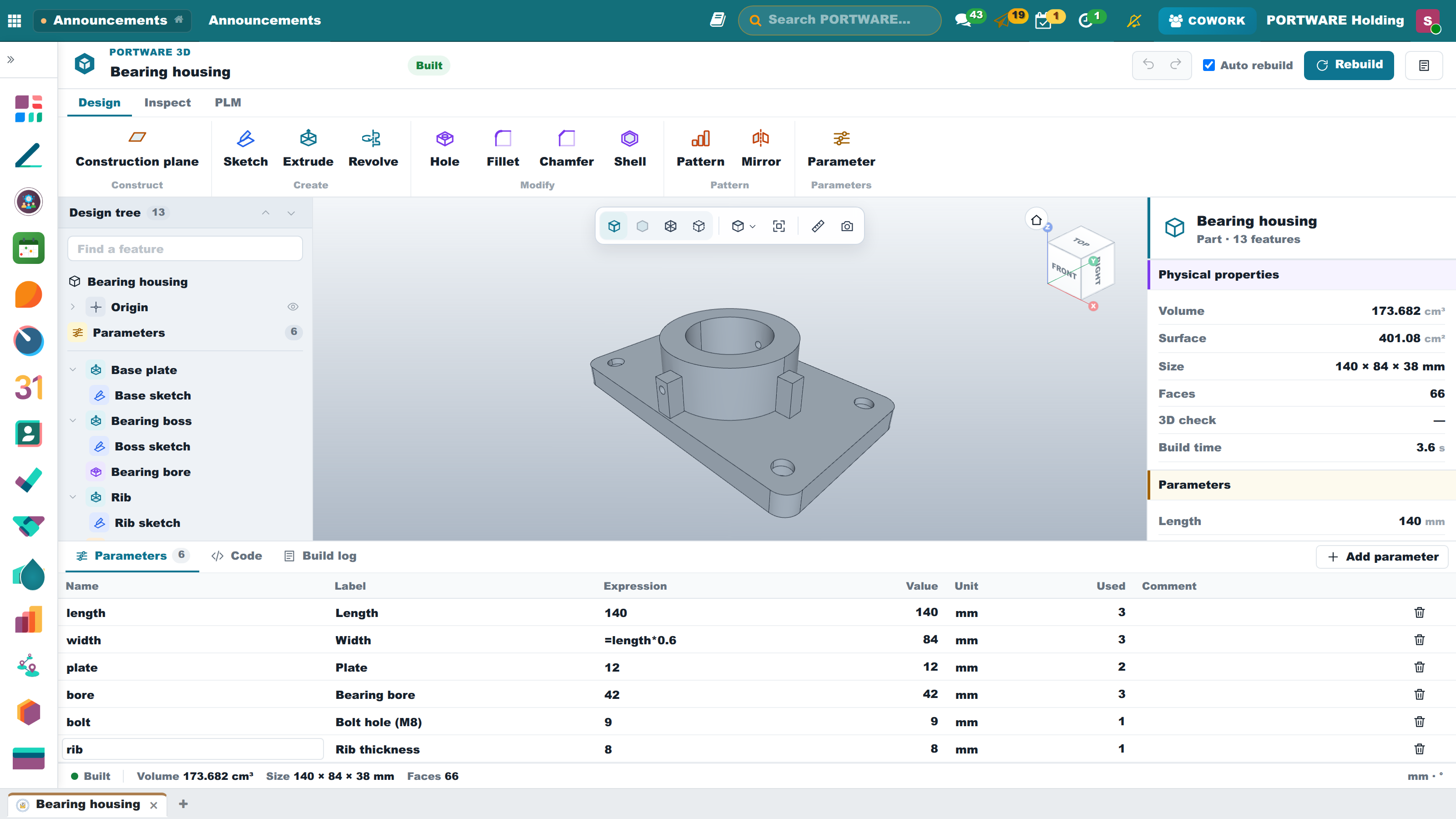
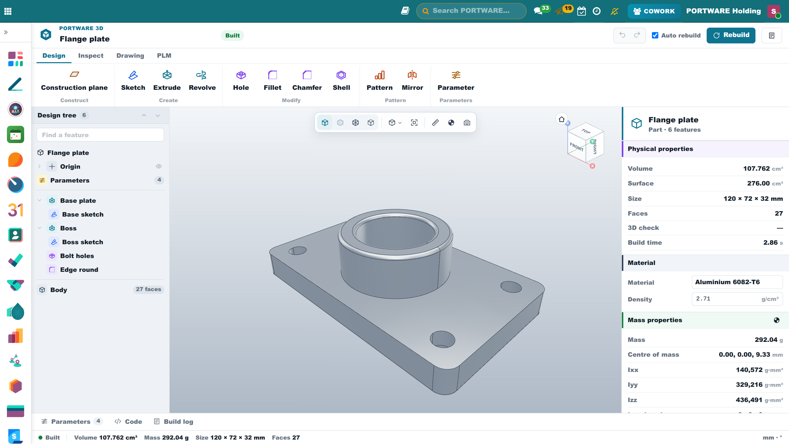
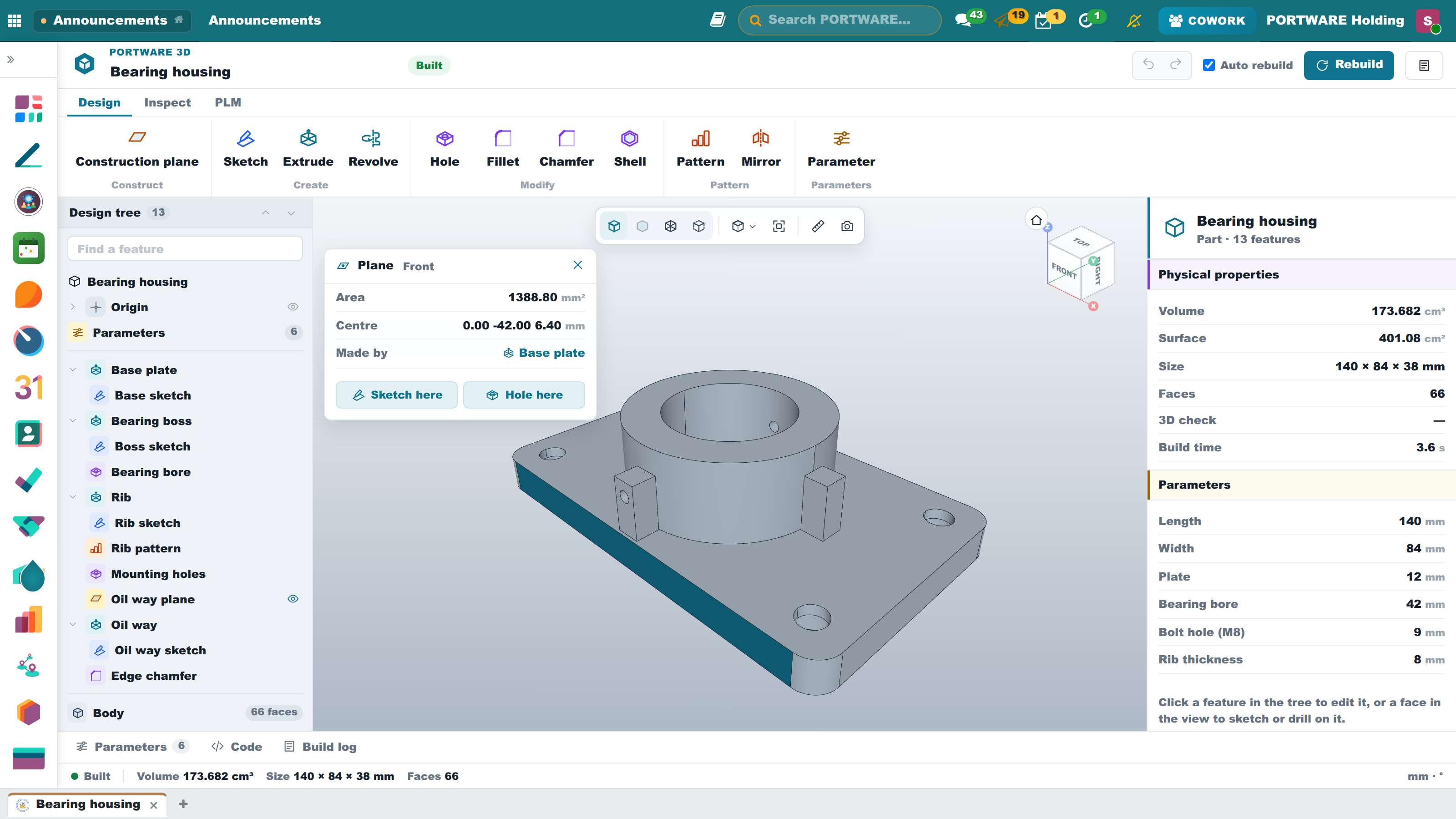
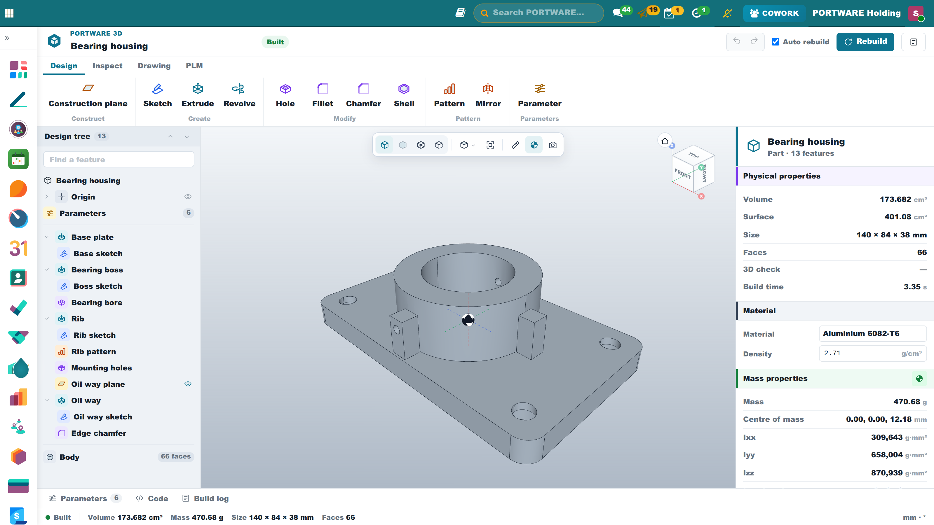
The design workbench: a parametric part as a feature tree
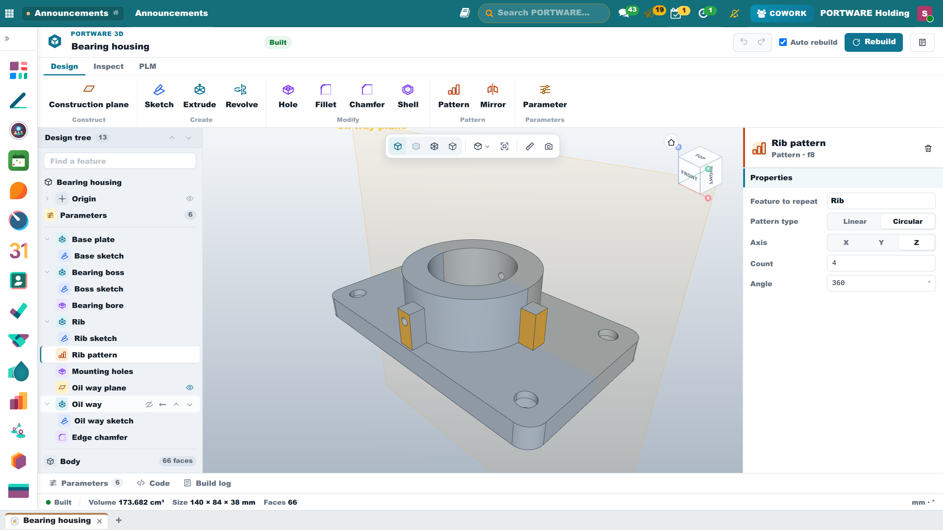
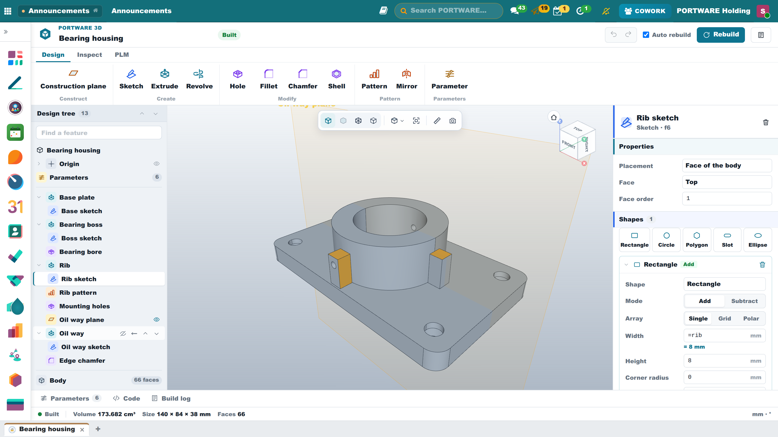
3D Design › New part (workbench) opens the part as a feature tree, as a CAD program does. Each kind of feature keeps one colour in the tree, the ribbon and the properties: construction plane amber, sketch blue, extrude and revolve teal, hole/fillet/chamfer/shell violet, pattern and mirror orange, parameters gold. The navigator on the left sits on a cool ground; the properties on the right are white with a band per section.
- The ribbon. Design tab: Construct (construction plane), Create (Sketch, Extrude, Revolve), Modify (Hole, Fillet, Chamfer, Shell), Pattern (Pattern, Mirror) and Parameter. Inspect tab: standard views, display modes, measure and picture. PLM tab: save to PLM, Hand over to production, 3D viewer and STEP.
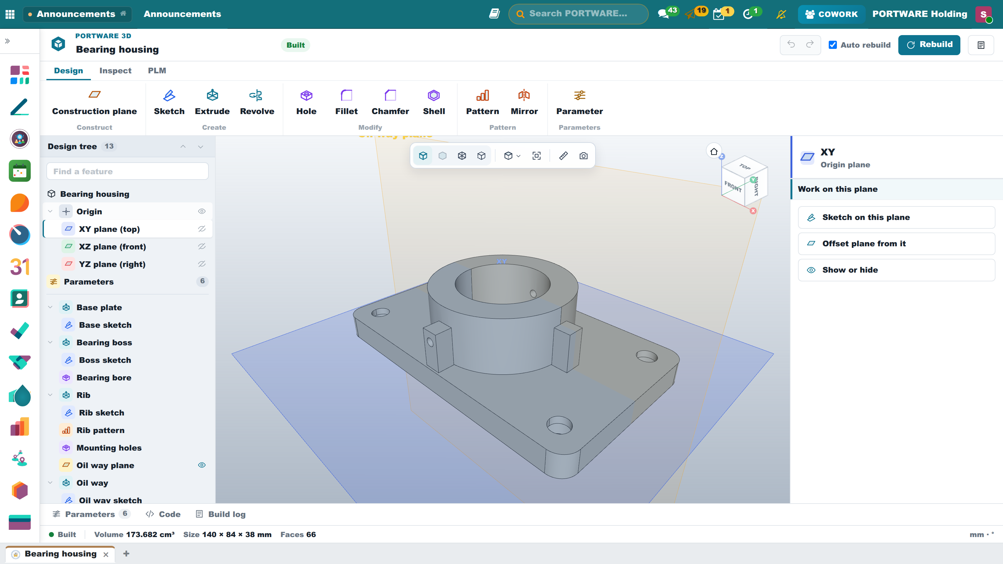
- The design tree. Origin planes (with eyes), parameters, features and the body. A sketch sits under the feature that uses it. The tree has a search box and expand/collapse all. Rows offer suppress, roll back to here and move up/down; a double click or F2 renames, Del deletes.
- Planes. XY blue, XZ green, YZ red, drawn translucent in the view. A picked origin plane offers Sketch on this plane and Offset plane from it. A construction plane stands at a distance from an origin plane and may tilt about X or Y; sketches sit on it, and it is drawn in amber.
- Properties. Every field of the picked feature can be edited and every size can be a formula (
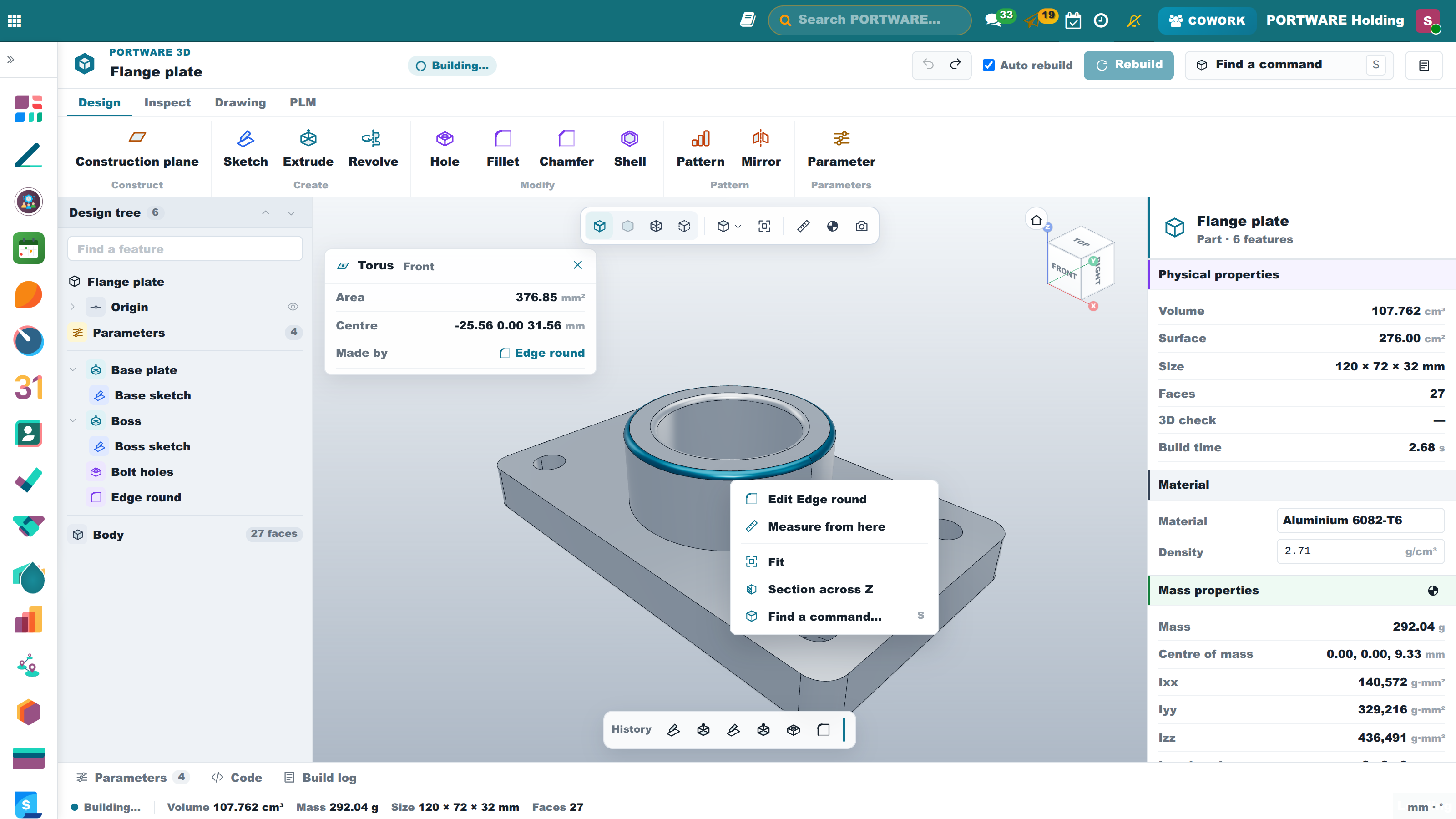
=width/2 + 5) whose value shows under the field. A sketch sits on a plane, a construction plane or a face of the body; the face is named by the way it looks and its order (the 1st upward face, the 2nd...). Pattern repeats an extrude or a revolve along an axis or around one. - Feature ↔ face. Picking a feature lights the faces it made, in amber. Clicking a face shows its kind, area, centre and the feature that made it; Sketch here and Hole here start a new feature on that face at the clicked point.
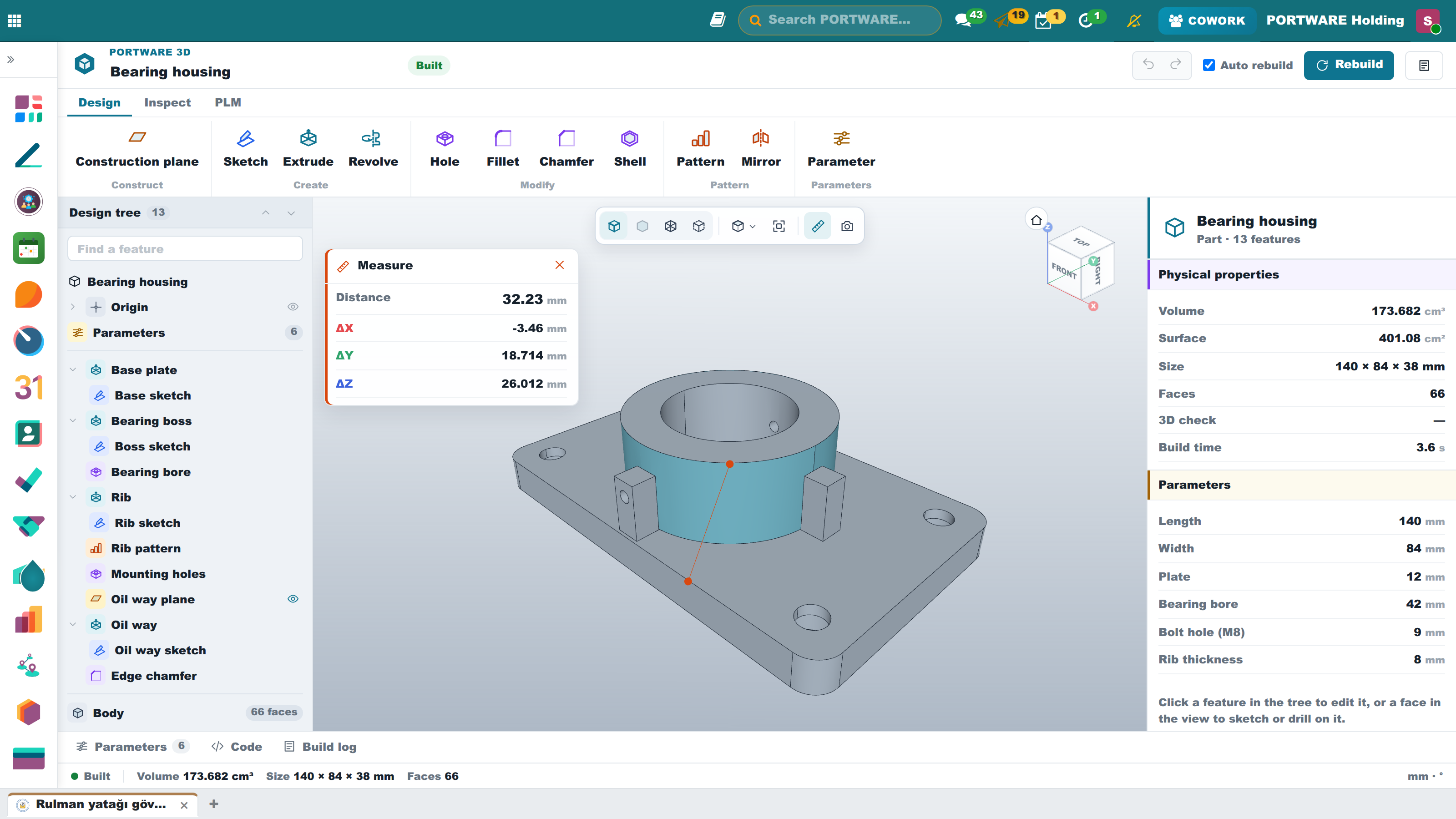
- The view. The view cube at the top right turns with the part; clicking a face, an edge or a corner looks from there, the home button goes back to isometric. The toolbar on top has shaded with edges, shaded, wireframe and see-through, the standard views, fit, measure and save a picture. Measure gives the distance between two points, its X/Y/Z components and the distance between two parallel flat faces.
- Parameters. The table below lists name, label, expression, value, unit and how many places use each; parameters may use each other. Code shows the build123d code the tree compiles to, Build log the last build.
Every change can be undone (Ctrl+Z, Ctrl+Y). With Auto rebuild on, the solid is rebuilt on the server in a few seconds; an error marks its feature in the tree and its field in red.
A feature tree from Cowork
Describe the part to Cowork: "design a housing for a 42 mm bearing with four ribs." Cowork first reads the feature catalogue and the manufacturability rules (ISO 273 clearance holes, counterbore sizes, wall thicknesses, edge breaks), then builds the part as a feature tree with its parameters. The tree is checked before anything is saved: on an error nothing is saved, and Cowork is told the feature and field to fix. The part opens in the workbench, where the engineer sees and changes every feature. Cowork can read an existing design and change it the same way. It picks the material itself ("aluminium" → 6082-T6), and "make its drawing" returns the PDF and DXF links.
The sketcher: constraints and dimensions
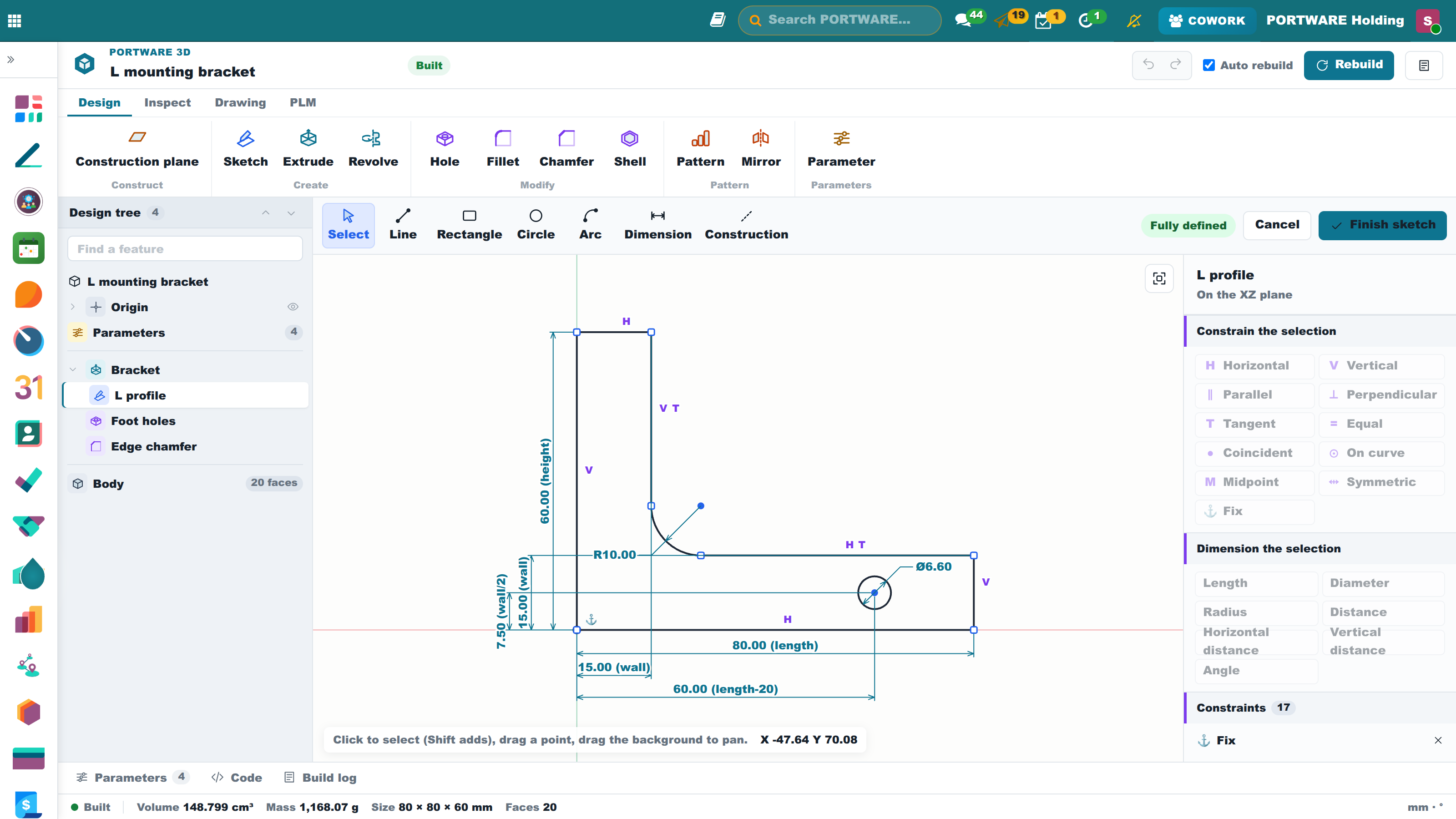
For a section the ready shapes cannot make (an L, a T, a cam, a lever), open the Sketcher on the sketch. Its tools are line, rectangle, circle, arc and construction geometry; segments that end on the same point are joined. A line drawn level or plumb gets its constraint on its own, and a click on the origin fixes the point there. The selection offers only the constraints it can take: horizontal, vertical, parallel, perpendicular, tangent, equal, coincident, on curve, midpoint, symmetric, fix. Dimensions are length, distance, horizontal and vertical distance, radius, diameter and angle; each is a number or a formula such as =wall/2.
The solver moves the geometry with every change, and a dragged point pulls the profile along its constraints. The status says whether the profile is fully defined, how many degrees of freedom are left or which constraints conflict. Dimensions sit around the profile as on a drawing. The server solves the sketch with the same algorithm, so a parameter changed in the workbench, on the form or by Cowork rebuilds the profile to its new sizes; a conflict is shown on the sketch with its id. An outline inside another becomes a hole.
Loft, sweep, draft and thread
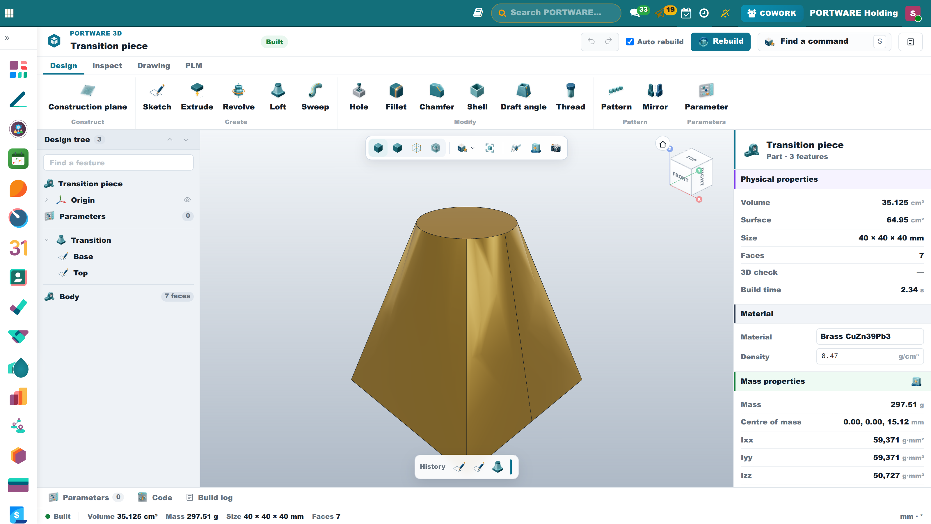
- Loft joins two profiles on different planes into one solid (a square-to-round transition, a funnel, a boss). The transition is smooth or ruled.
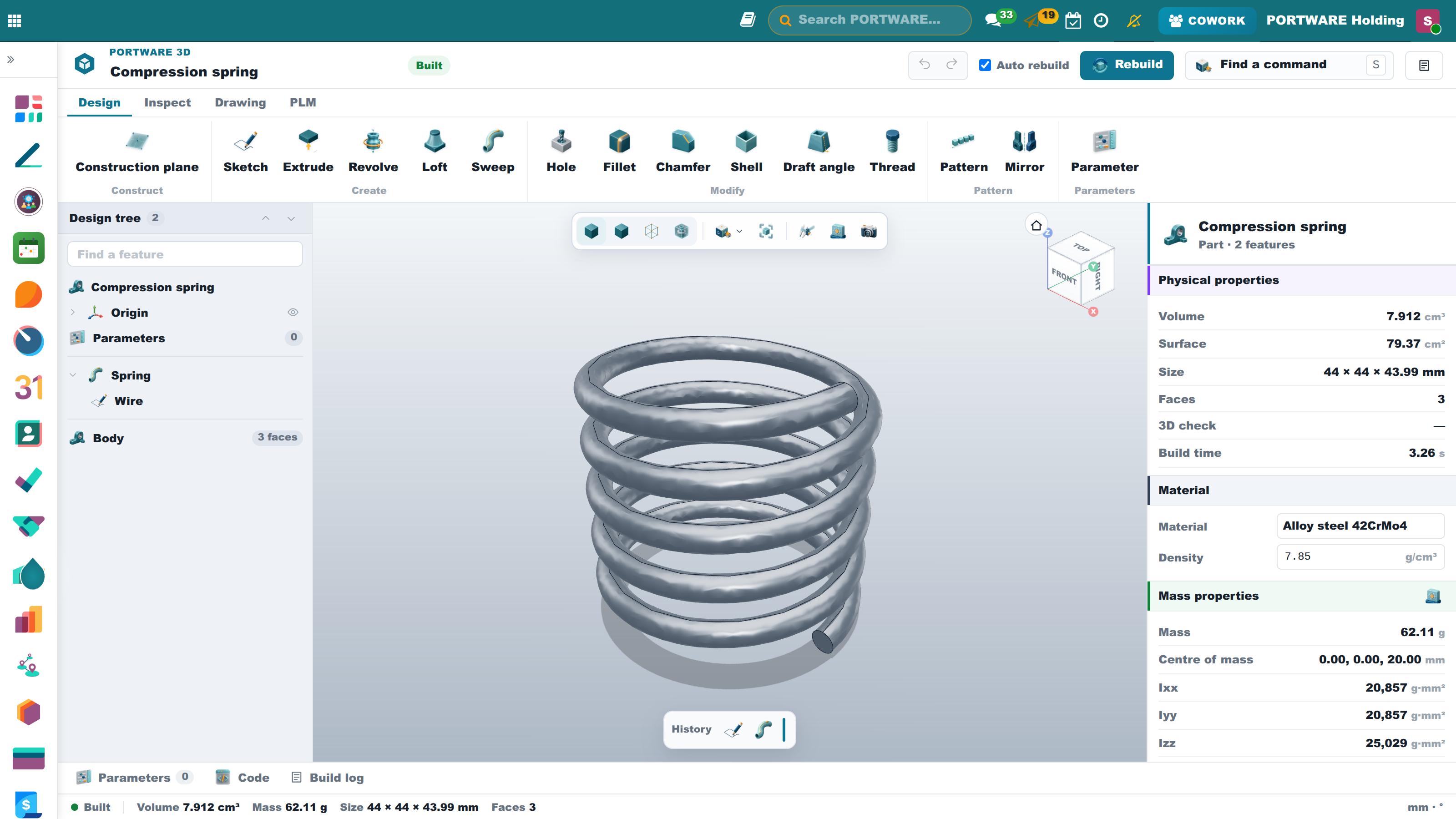
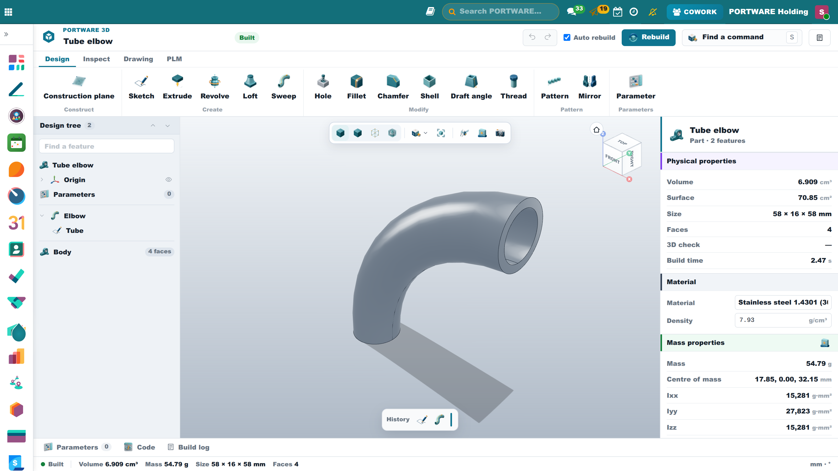
- Sweep carries a profile along a path. The path is a helix (a spring, a coil: coil radius, pitch, height) or a bend (a tube elbow: bend radius and angle). The profile is set square to the path at its start by itself.
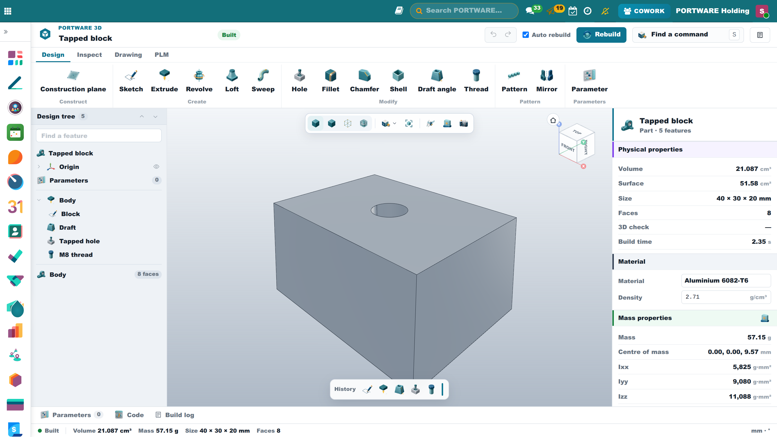
- Draft gives the side faces a release angle; the part narrows away from the neutral face (bottom or top).
- Thread puts a cosmetic metric thread on a hole (M3–M24, ISO 261). The model keeps the tap drill; the drawing note says "thread M8×1.25, 12 deep", and names the right drill when the hole differs from it.
The tool icons on the ribbon, the tree, the history, the command search and the right-click menu are in PORTWARE's 3D icon language and follow the style the user chose (solid or glass).
Working fast: command search, right click, history and section
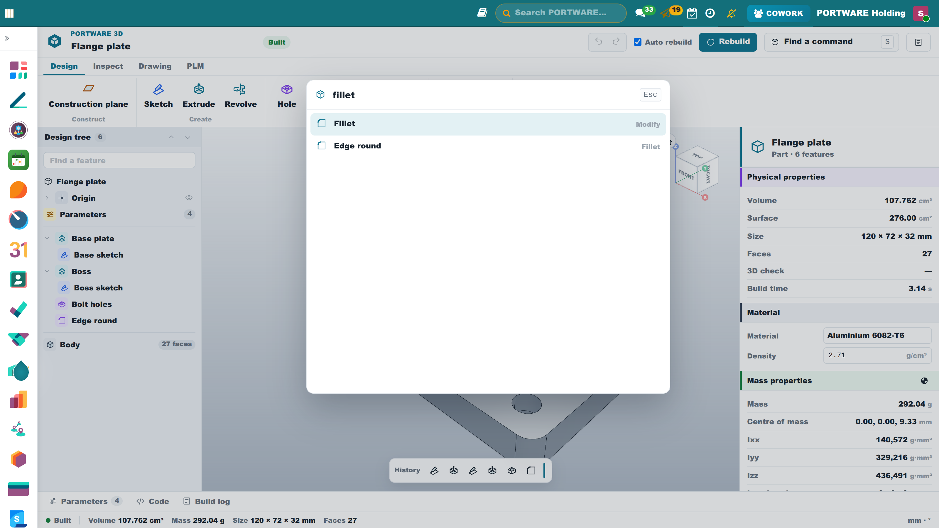
- Command search: S or the Find a command box in the header finds every command, view and feature by name; Enter runs it.
- Right click: right click a face in the view for what fits it: sketch or hole here, edit the feature that made it, measure from here, look at this face. Right click a feature in the tree or the history for edit, rename, suppress, roll back to here, move and delete.
- History: the strip under the view shows the features in build order; the rollback bar shows where the model stops, a red underline marks a feature in error.
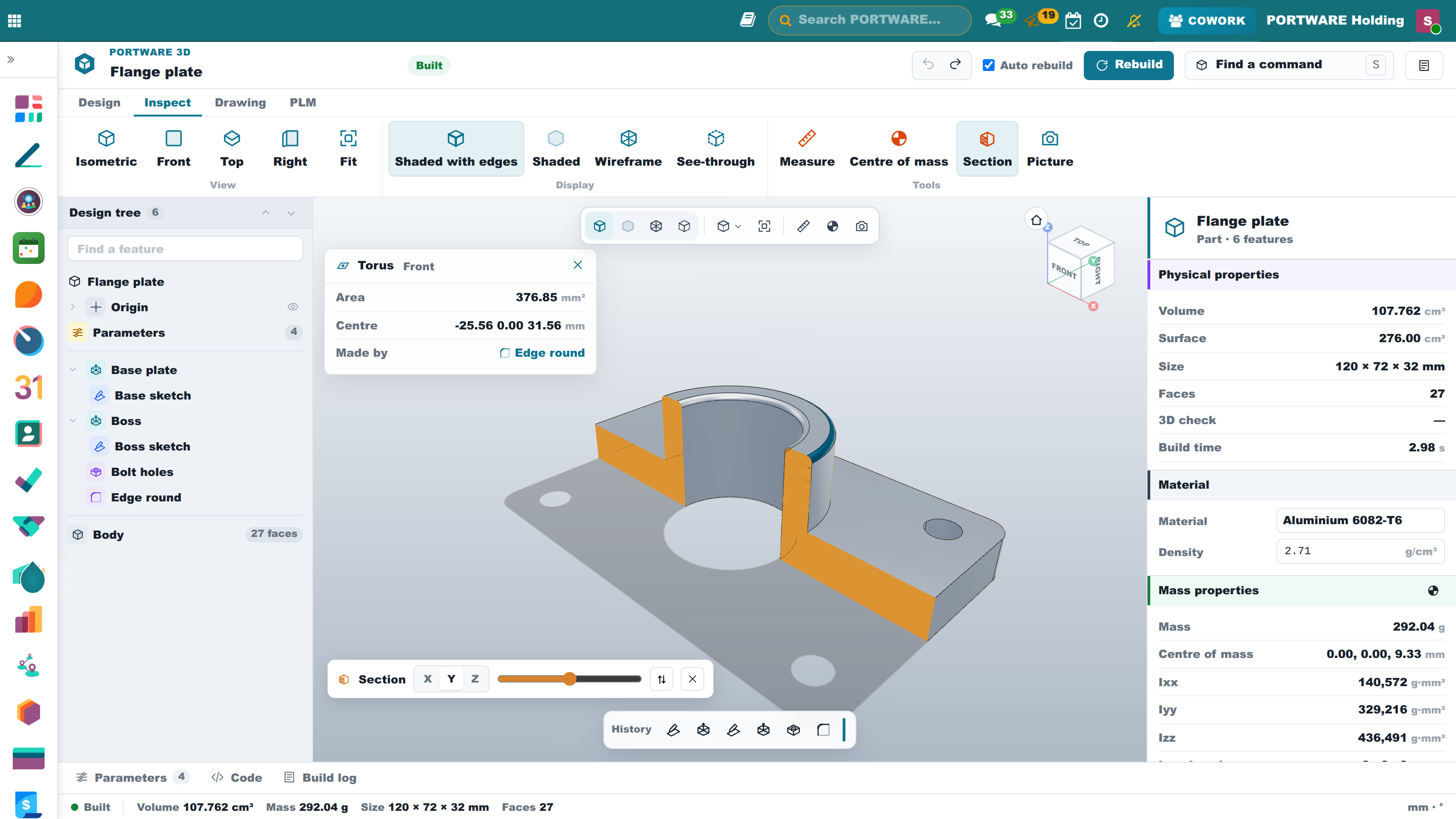
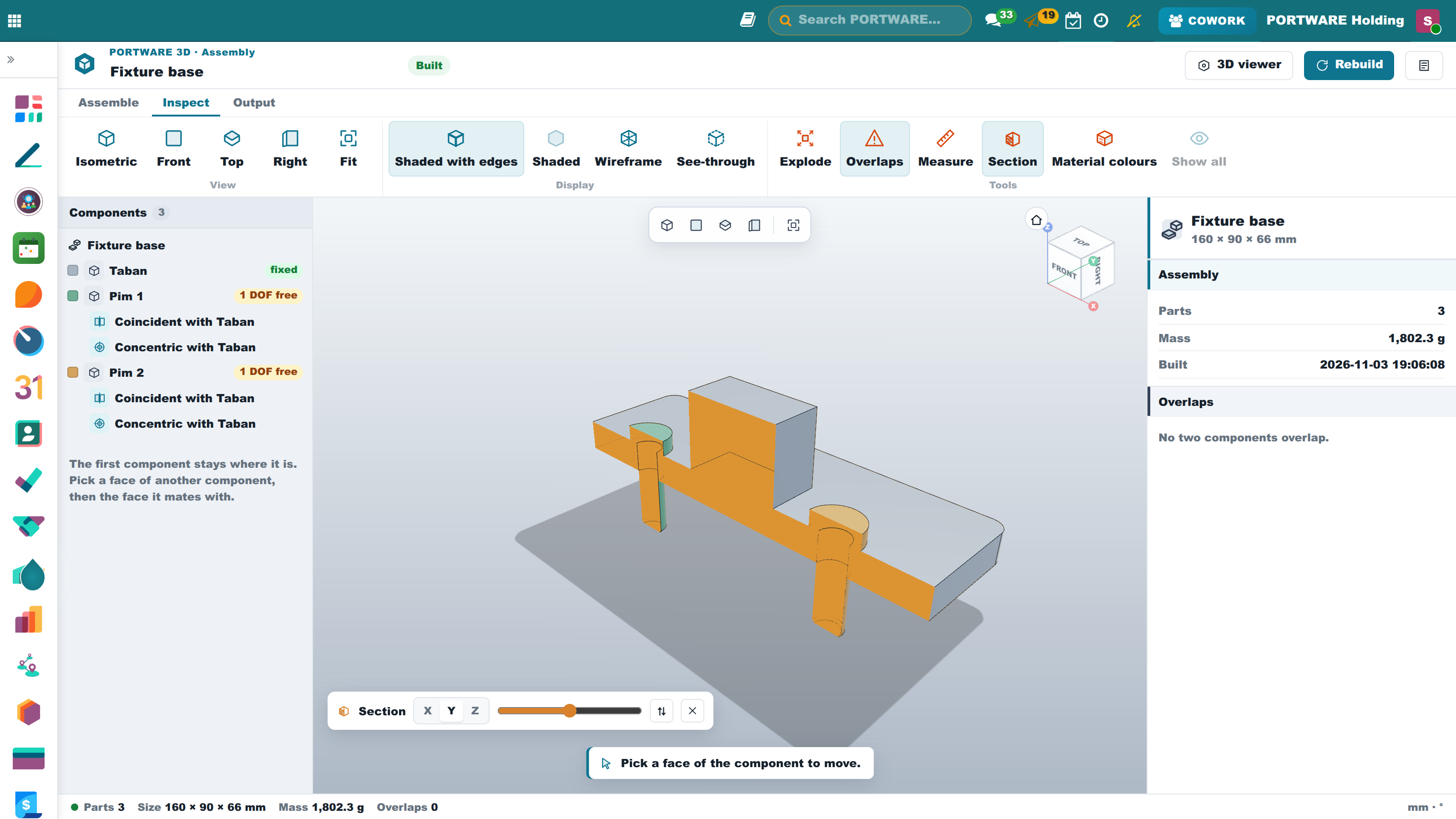
- Live section: Inspect › Section cuts the part with a plane square to X, Y or Z; the cut face shows in orange. The slider moves the plane, ⇅ swaps the side. The assembly workbench has the same section.
Material and mass
The part is drawn in its material's look (aluminium silver, steel grey, brass yellow, plastics matt) under a studio light with a shadow on the floor; changing the material changes the look.
With nothing picked, the right panel has a Material section: the company's PLM materials first, then standard engineering materials (S235JR, C45, 42CrMo4, 1.4301, 1.4404, EN-GJL-250, aluminium 6061/6082/7075, brass, copper, titanium, POM, PA6, ABS, PLA, PEEK). The density can be typed too. Mass properties shows the mass, the centre of mass and the moments of inertia (g·mm²) from the exact solid; a new material needs no rebuild. The button in its header shows the centre of mass and the principal axes in the view.
Drawing
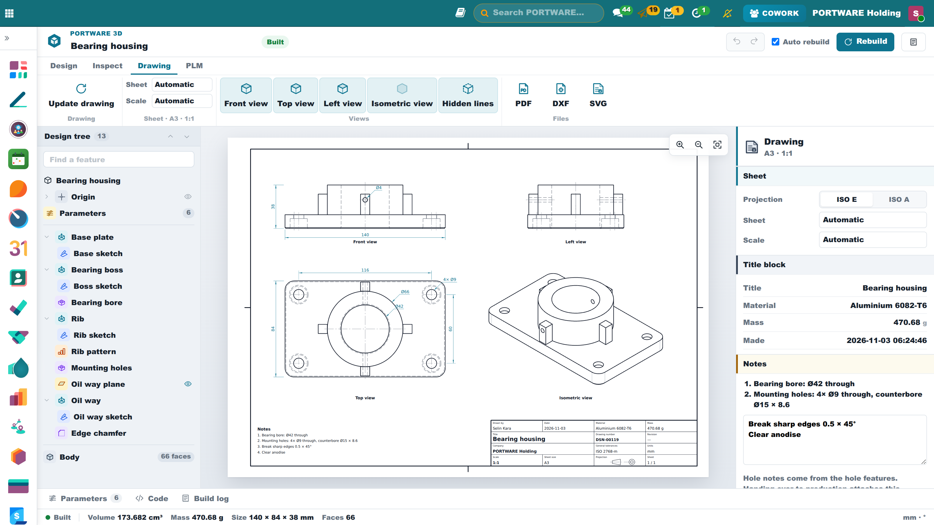
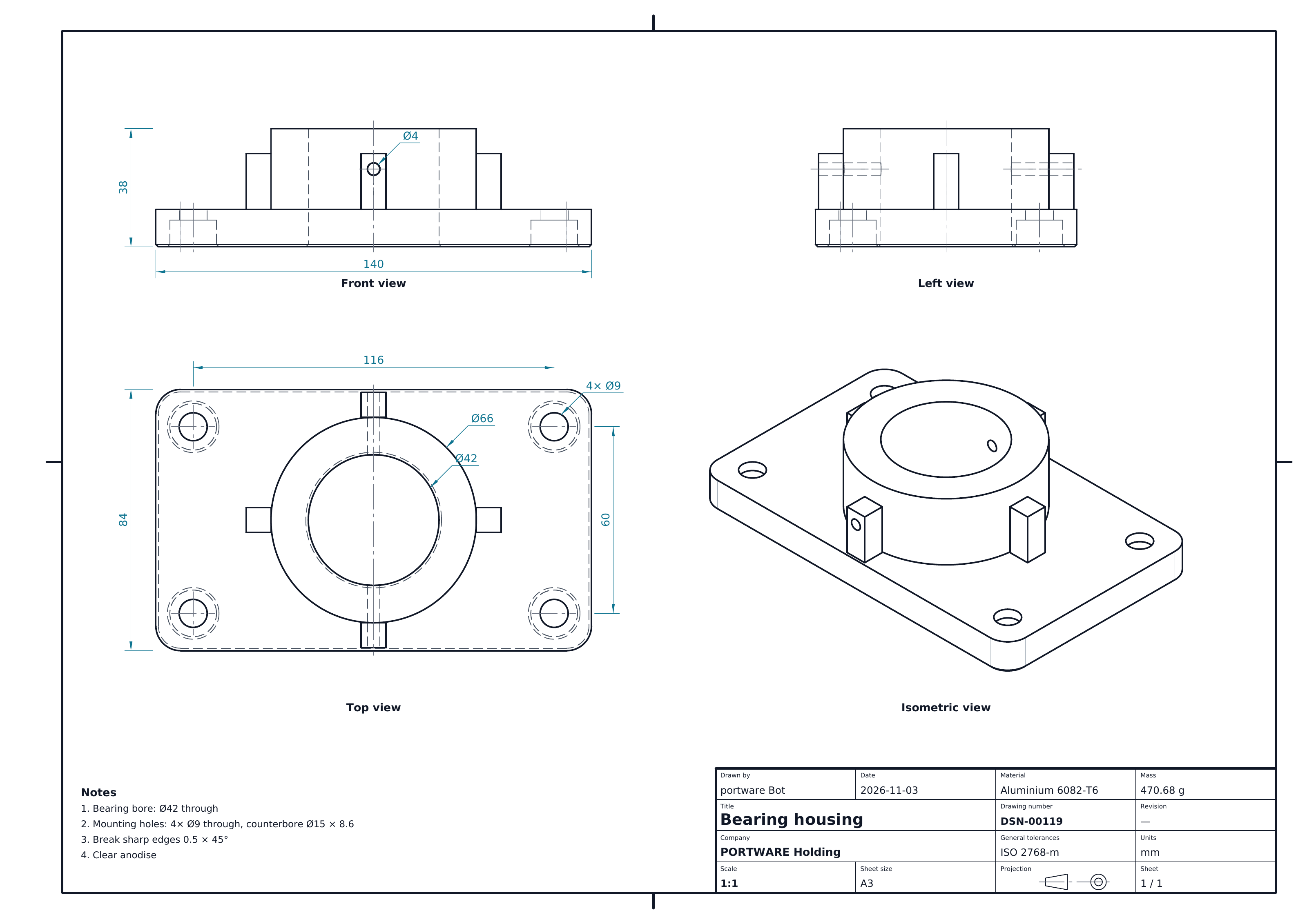
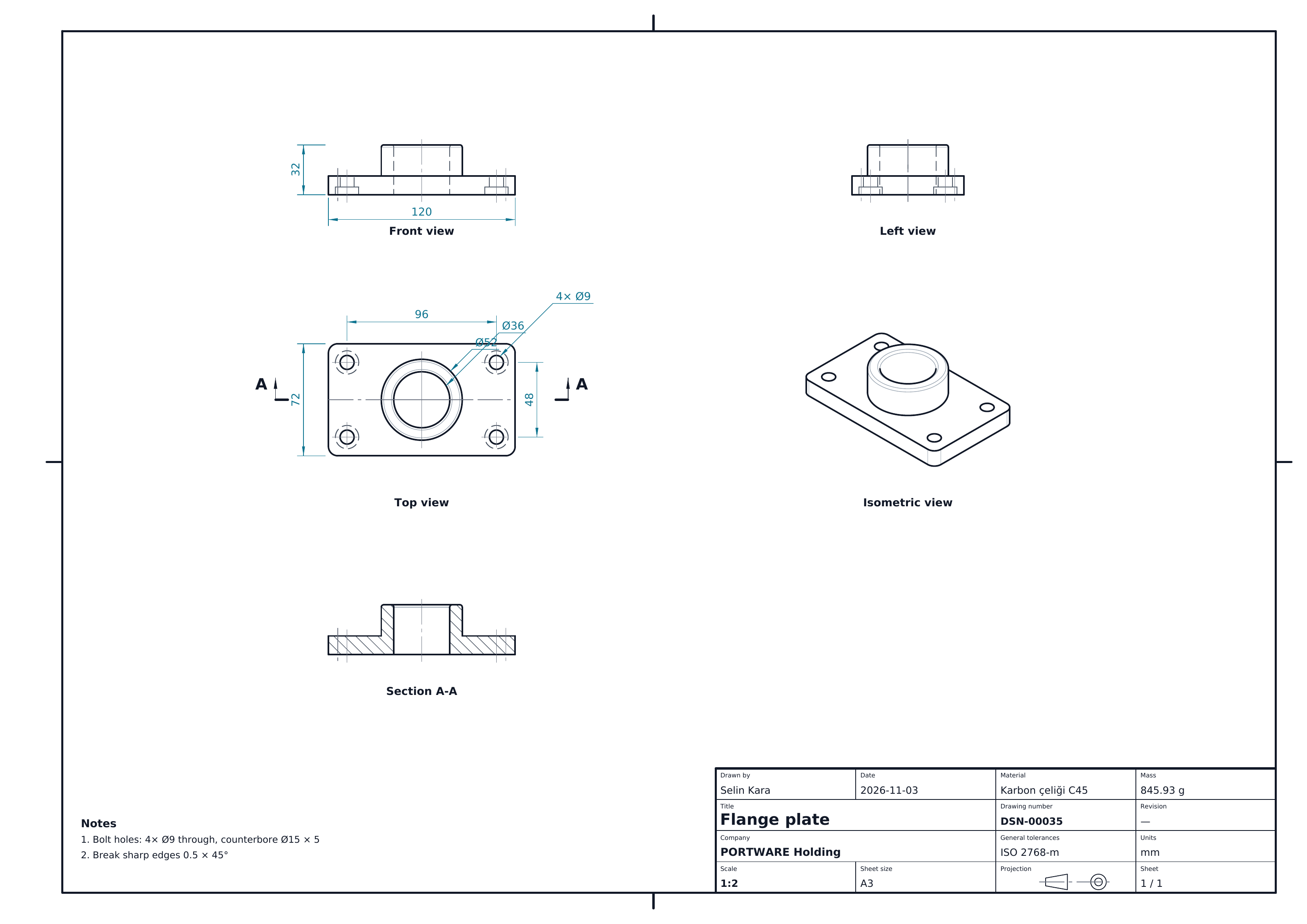
The Drawing tab makes the part's manufacturing drawing. Front, top, side and isometric views are projected from the exact solid with hidden-line removal, in first-angle projection (ISO E) by default or third angle (ISO A). The drawing gets on its own:
- centre lines on holes and shafts,
- overall sizes and hole spacing,
- diameters with their count ("4× Ø9"),
- hole notes from the hole features, with the counterbore,
- an ISO 7200 title block with material, mass and general tolerances.
Sheet (A4–A1) and scale (ISO 5455 series) are chosen for you or set by hand. Notes go one per line. Download it as PDF, DXF (layered, for laser, CAM and CAD) or SVG. When the part changes, the tab says the drawing is out of date.
Section A-A adds a full section to the drawing, parallel to the front or the side view. The plane runs through the largest and most hole axes by itself, through the middle when there are none. Cut faces are hatched to ISO 128. The section sits under the view it is aligned with. The top view shows the cutting line with arrows and the letters A. Counterbores, blind holes and inner grooves read clearly in a section.
Hand over to production
PLM › Hand over to production makes a built design a product (or uses its product) and puts it on the manufacture route. It attaches the STEP file and the drawing's PDF and writes the weight and volume on the product. Where PLM is installed, it also sets the product's raw material and saves the design to PLM. Handing over again refreshes the files on the same product.
Assemblies
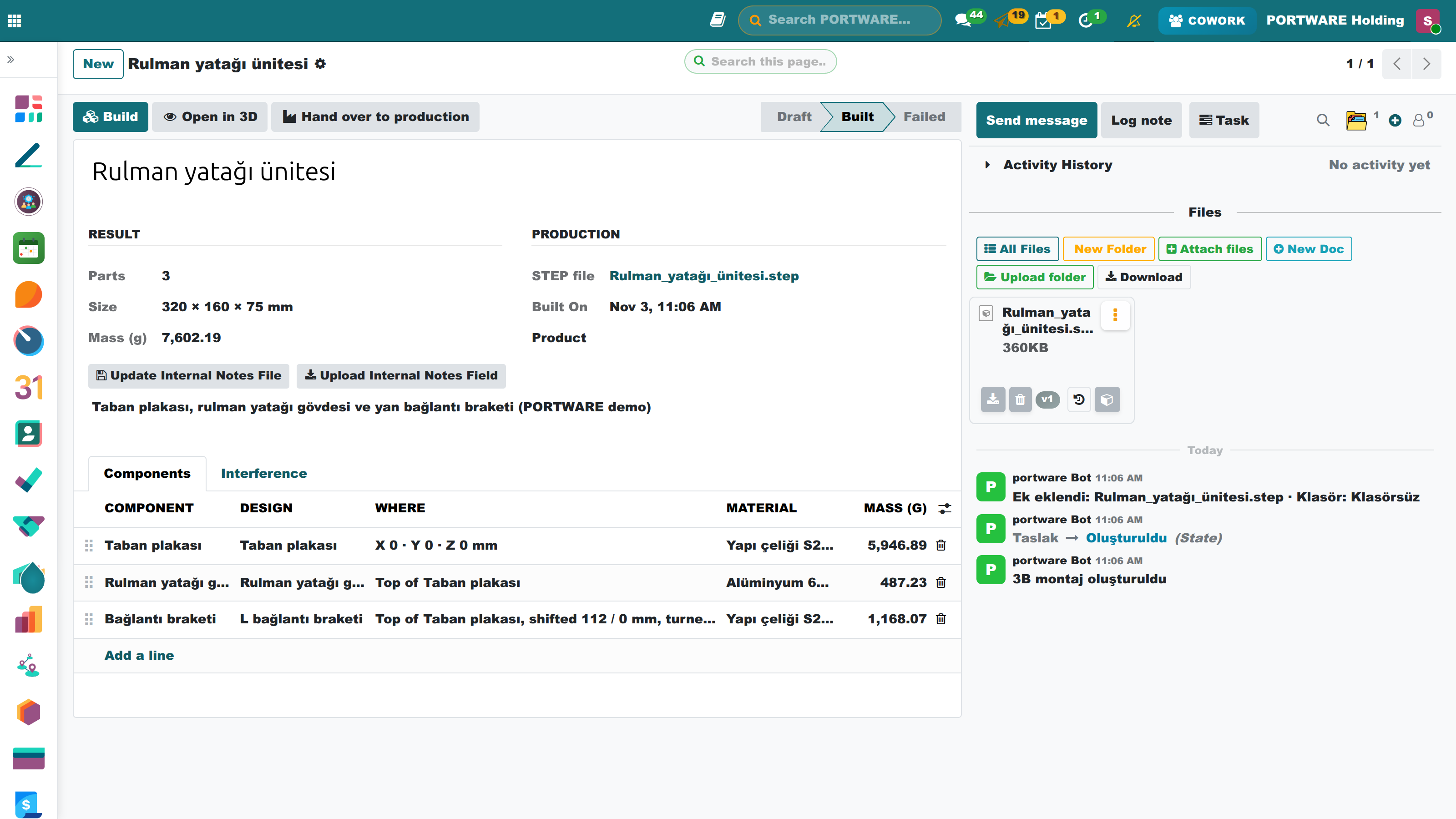
3D Design › Assemblies puts designs together. Each line places a design at a position (X, Y, Z and rotations) or on a face (top, bottom, front, back, left, right) of a component listed before it. A component set on a face is centred on it; it can be shifted along the face, held a gap apart and turned about the face's normal. Build makes every component from its design, places it and writes one STEP with each component named. The assembly opens in the 3D viewer with its parts tree, section and exploded view. Components that overlap are listed with the overlapping volume on the Interference tab. While they do, Hand over to production refuses; otherwise it makes the assembly's product, each component's product and a bill of materials with the quantities. Cowork can assemble too ("put the housing on the plate and the bracket beside it").
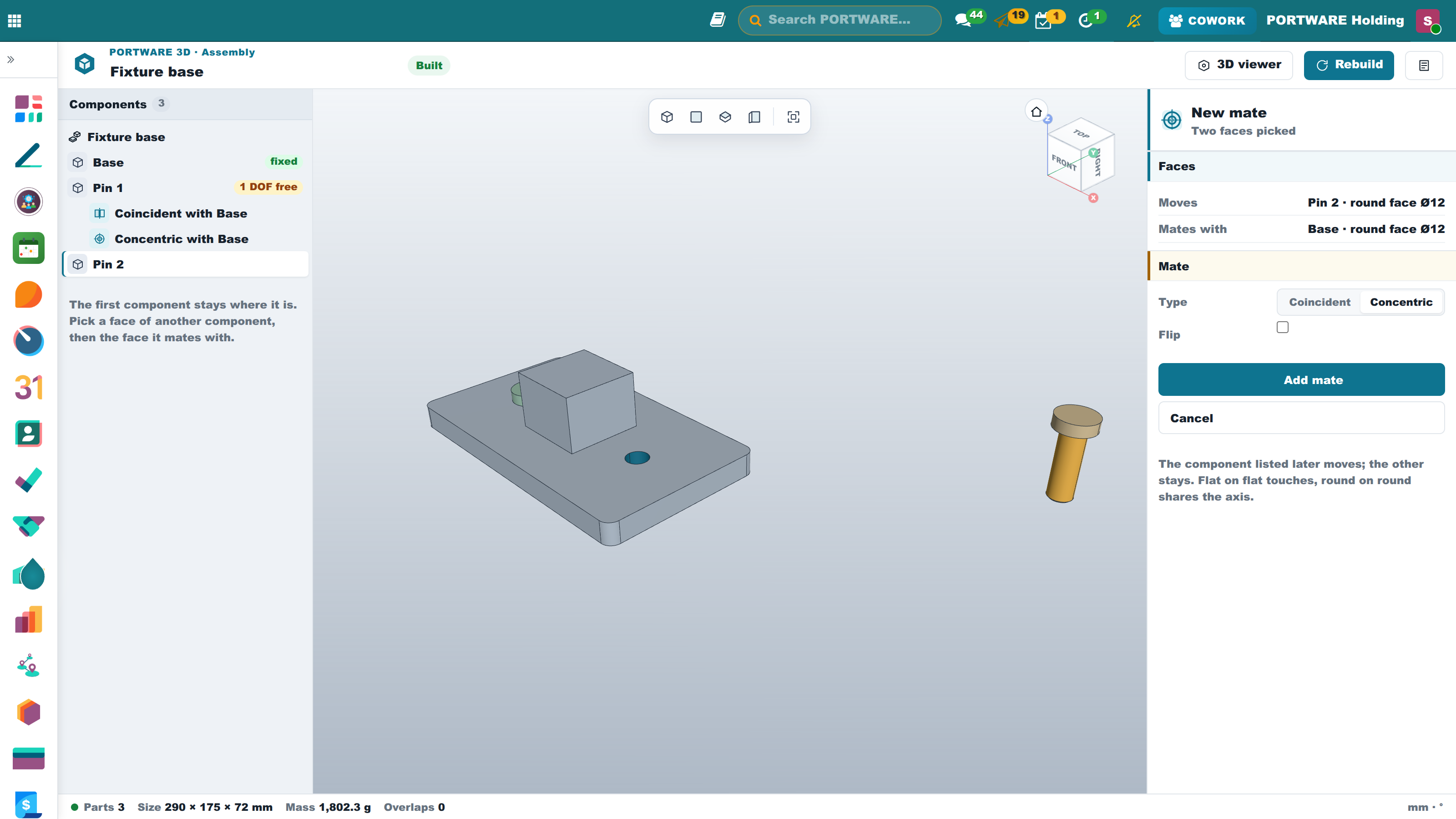
Mates: assembling by picking faces
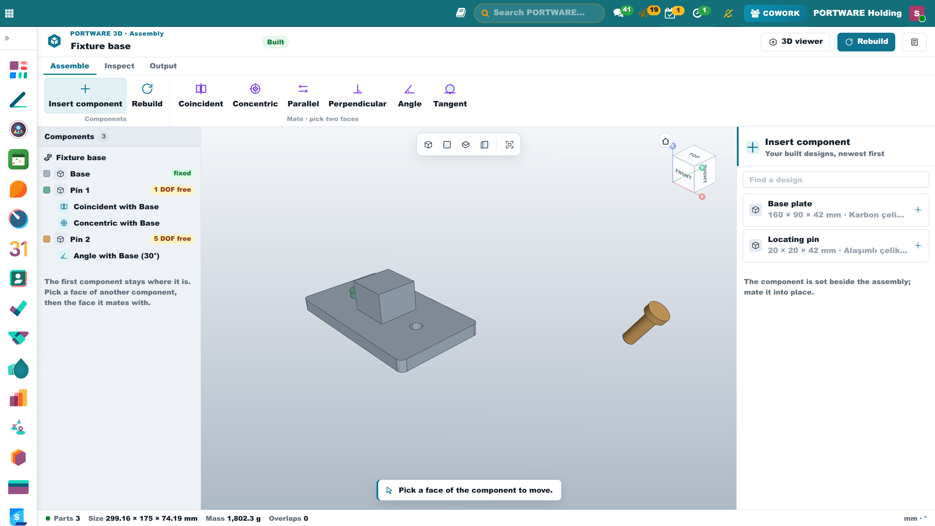
Mate in 3D on the assembly form opens the assembly workbench, each component in its own tint; the tree carries its colour tag, an eye (hide) and Show only this. The ribbon has three tabs:
- Assemble: Insert component lists your built designs and sets the one chosen beside the assembly. A mate type can be chosen in advance.
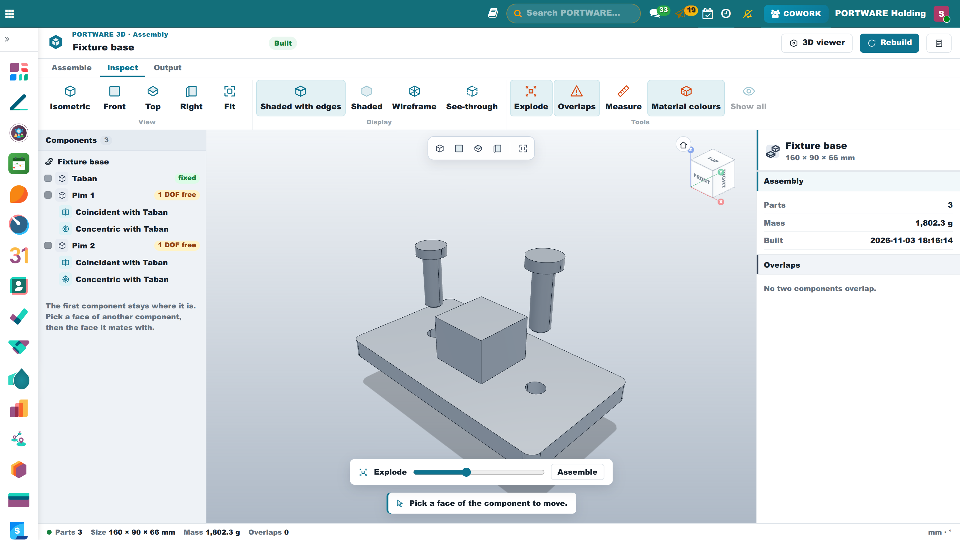
- Inspect: standard views, display modes (with edges, shaded, wireframe, see-through) and tools. Material colours draws each component in its material's look. Explode pulls parts apart along the way they were mated; a slider sets the distance. Overlaps paints overlapping components red. Measure gives the distance between two points and between parallel faces.
- Output: STEP, the 3D viewer, a picture and Hand over to production. Click a face of the component to move, then a face of a component before it. The type
follows the faces:
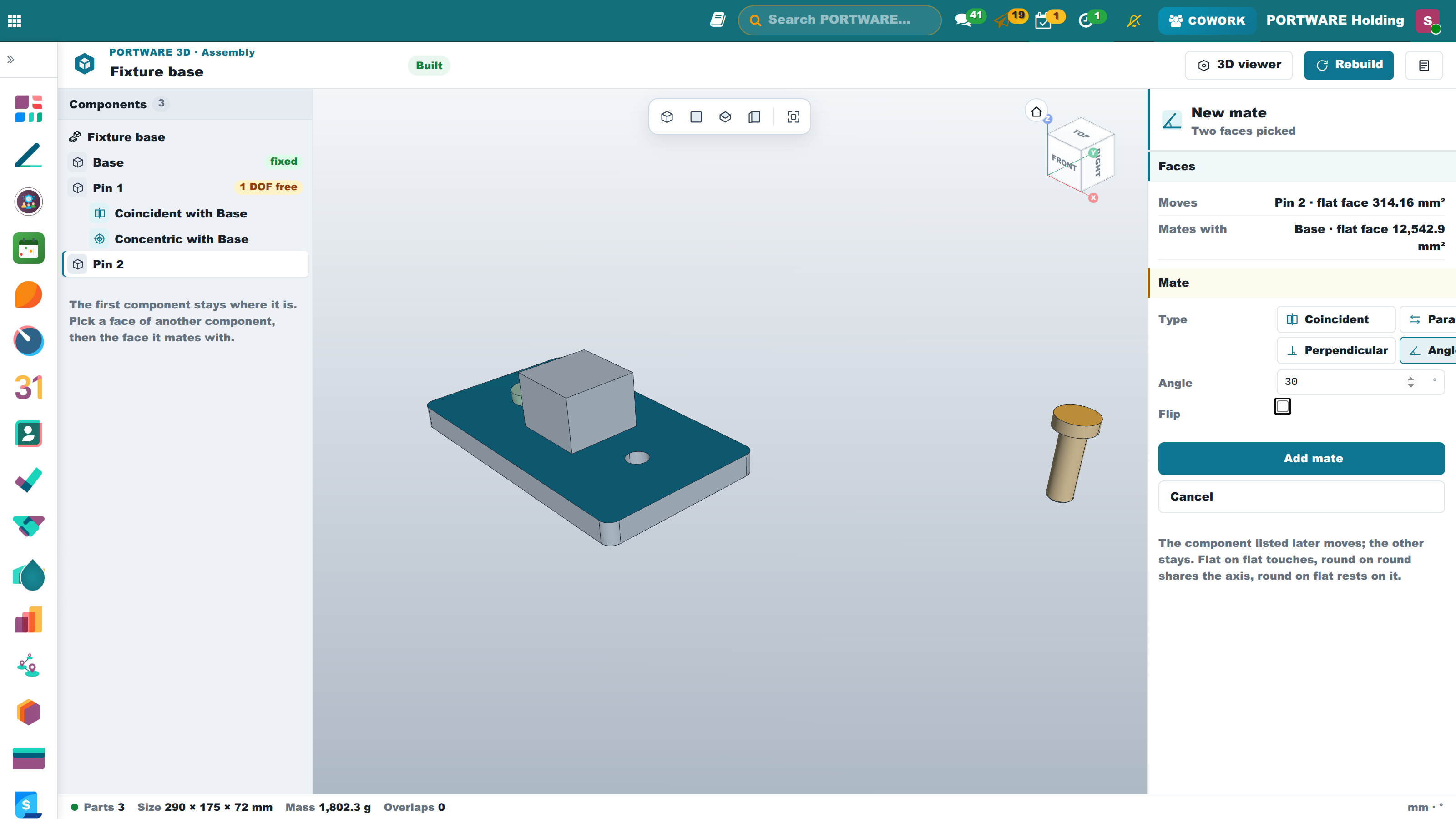
- two flat faces make a coincident mate: they touch, or stay a distance apart;
- two round faces make a concentric mate: a pin and its bore share one axis.
Other types follow the faces picked:
- two flat or two round faces can be held parallel, perpendicular or at an angle;
- a round face rests tangent on a flat one (a roller on a plate).
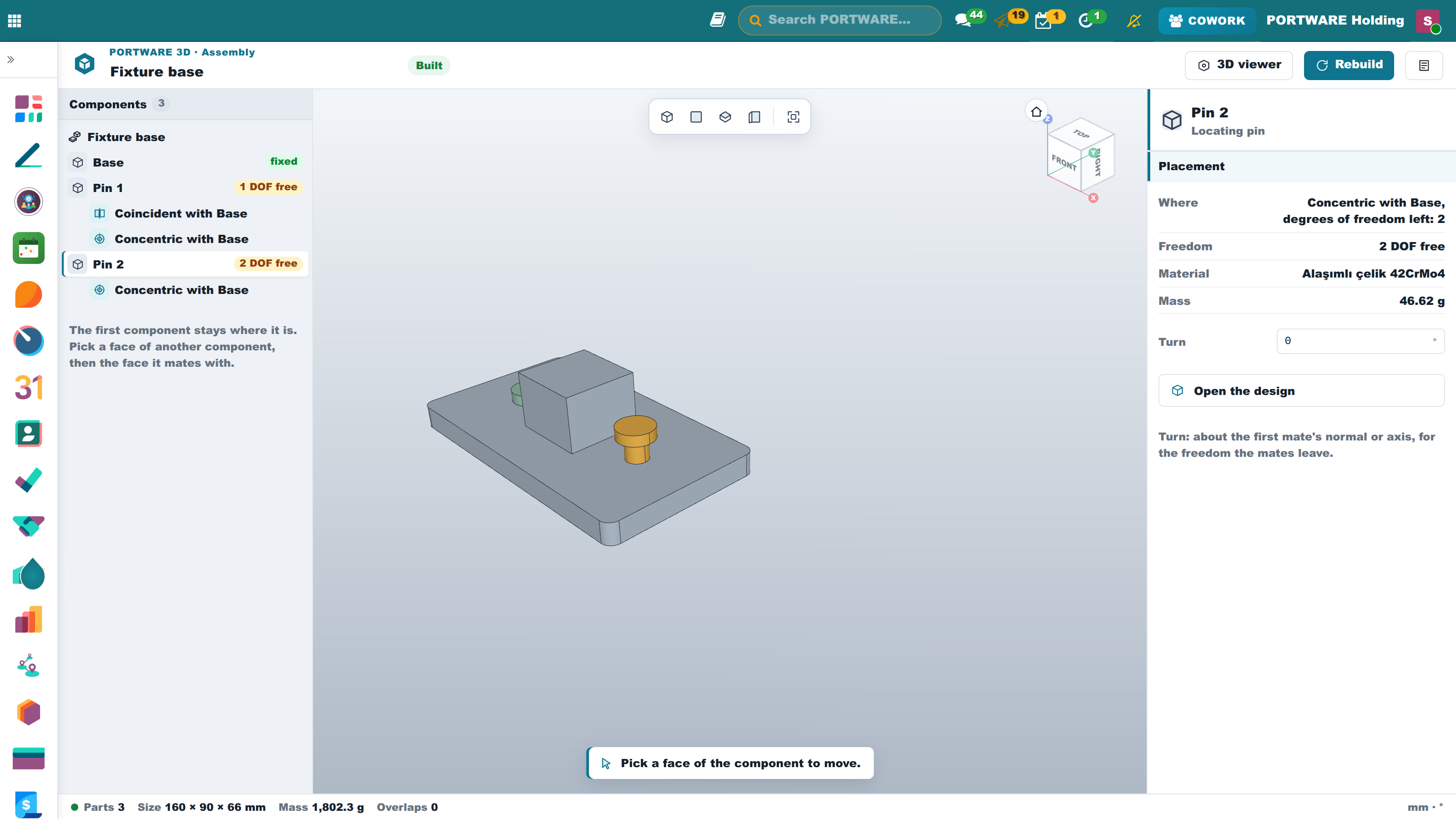
A mate on directions only turns the component where it stands. Flip turns the faces to look the same way, or the axis round. The component listed later moves; the first component stays where it is. The assembly is built again after each mate. The tree shows the freedom each component keeps: "1 DOF free" says a pin can only turn about its own axis. Mates that cannot all hold are an error that says which to remove. Turn rotates the component about its first mate's axis, for the freedom the mates leave.
A mate keeps the kind, area, centre and direction of each face picked. When the design changes and its faces are numbered anew (a chamfer added, say), the face is found again from that signature and the mate follows by itself. Cowork mates too: it reads a component's faces, then makes mates such as "the pin concentric with the bore, its head coincident with the plate" and says what freedom is left.
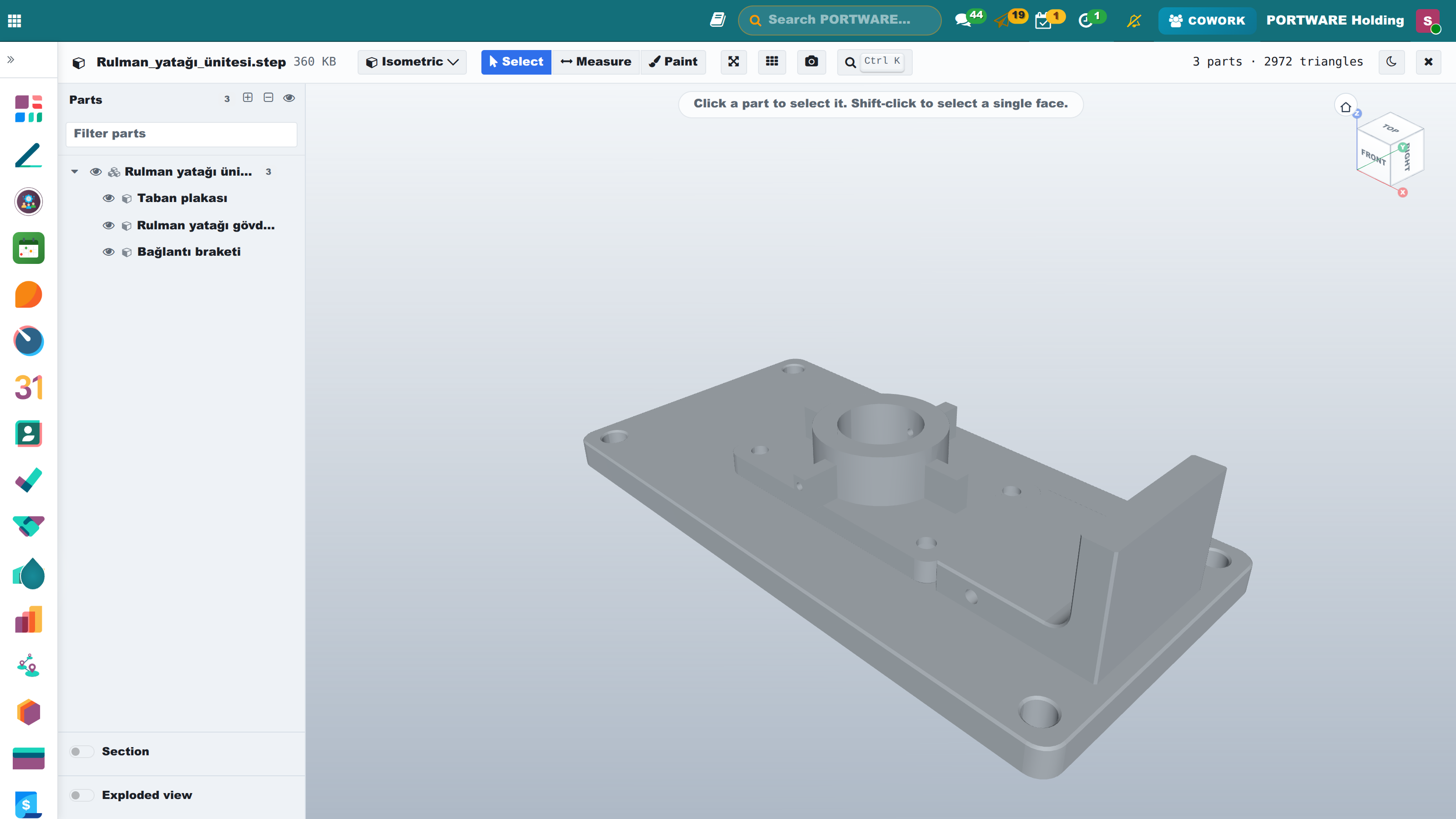
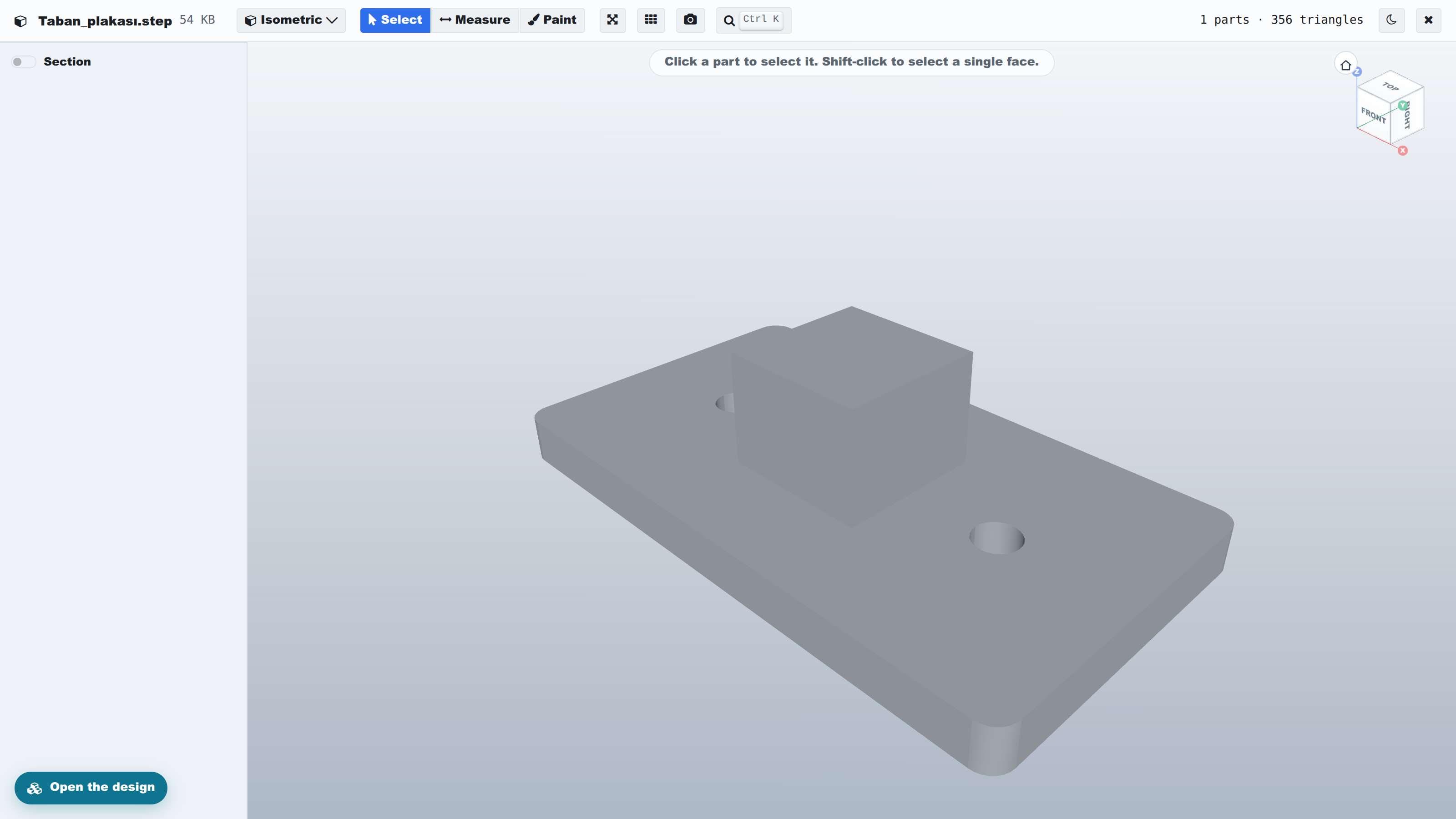
A STEP from a design or an assembly, even copied onto a task or a product, shows Open in the design workbench bottom left in the 3D viewer; for a design written as code it opens the design's form.
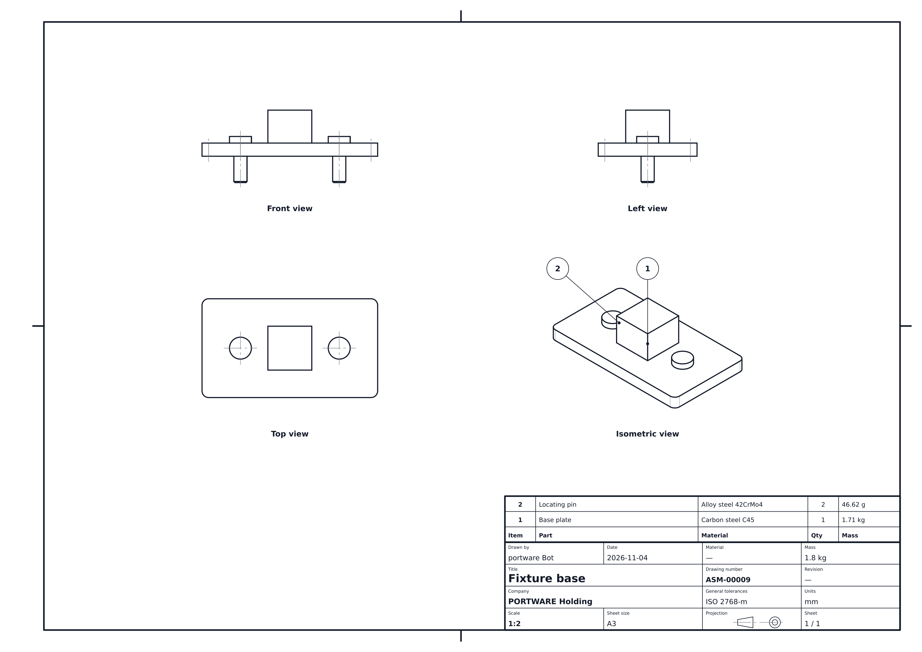
Assembly drawing
Output › Assembly drawing on the assembly workbench, or Assembly drawing on the form, makes the assembly's drawing as a PDF:
- front, top, side and isometric views, in the projection method chosen on the form;
- the parts list on the title block (ISO 7573): item, part, material, quantity and mass; a design is listed once with its count;
- one balloon per item on the isometric view (ISO 6433), its leader ending on a face of the part you can see.
An assembly drawing carries no dimensions: they are on the parts' own drawings. Material names are written in the reader's language. Hand over to production makes the assembly drawing afresh and puts it on the product.
Ready designs
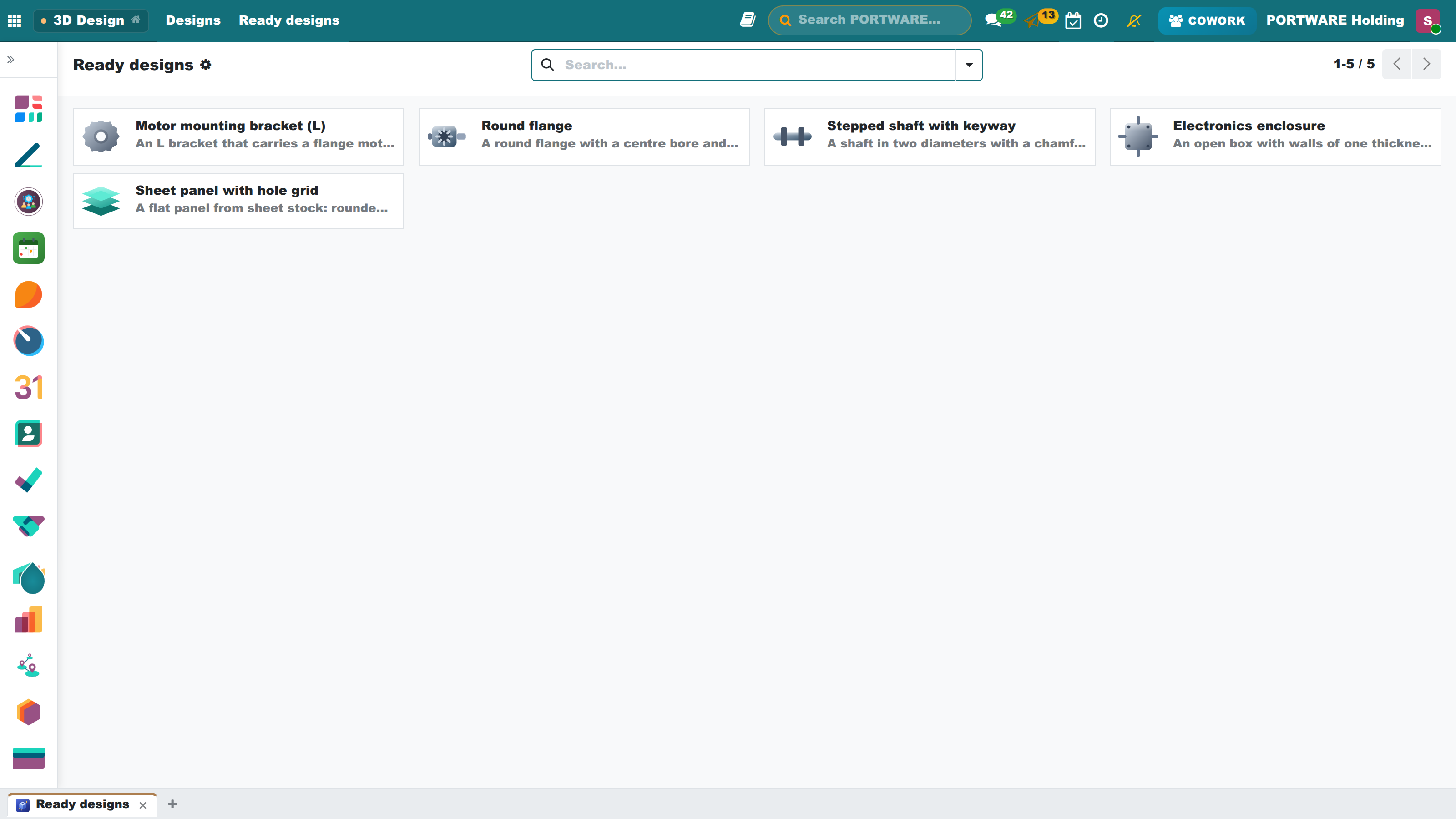
| Design | Numbers you change |
|---|---|
| Motor mounting bracket (L) | flange, spigot, bolt circle, plate thickness, base depth |
| Round flange | diameter, thickness, bore, bolt circle and count, hub |
| Keyed stepped shaft | two diameters and lengths, key width, depth and length, chamfer |
| Electronics enclosure | size, wall thickness, corner radius, mounting bosses |
| Sheet panel with hole grid | size, sheet thickness, mounting and ventilation holes |
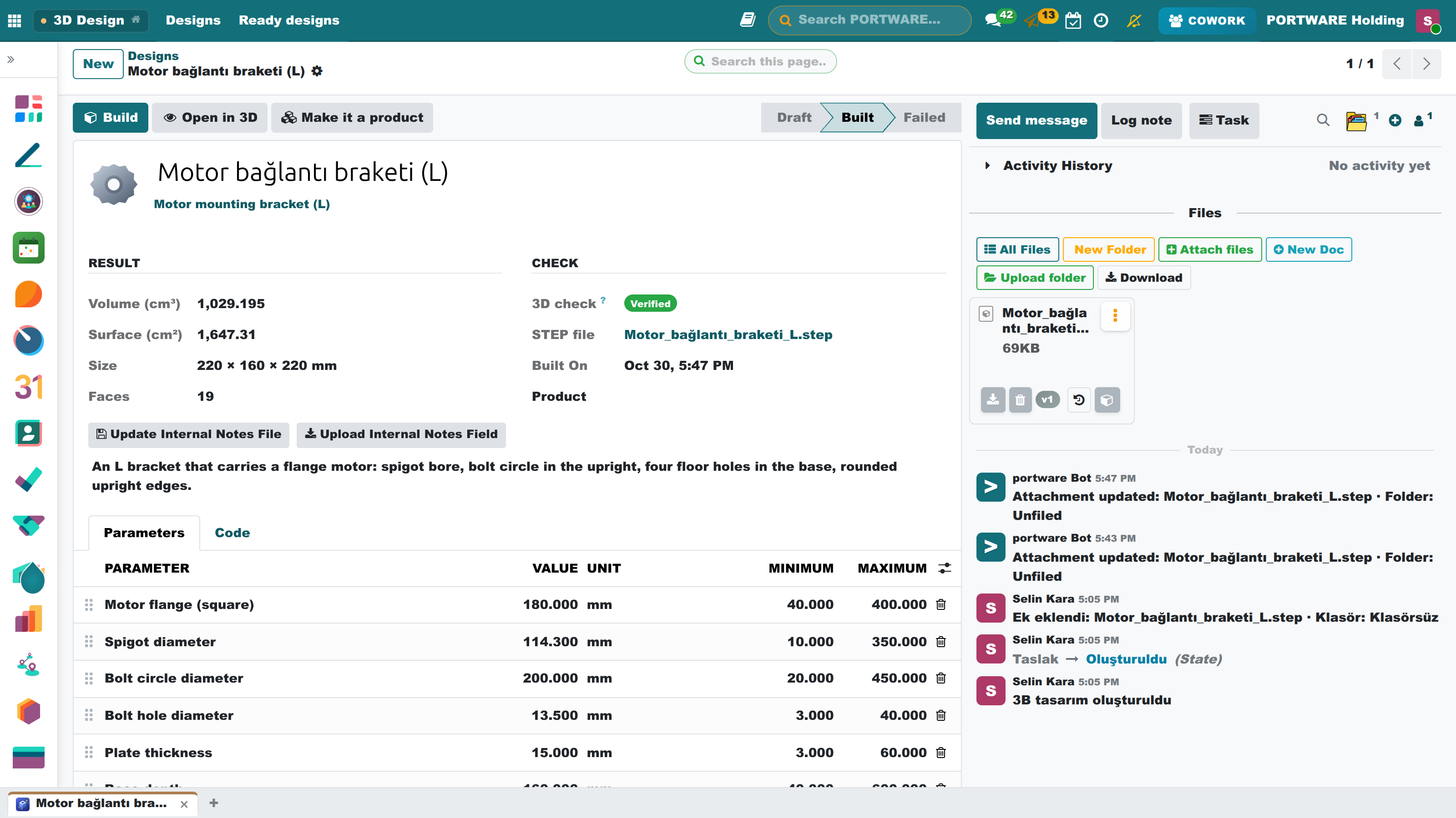
Use this design opens your own copy; change the numbers in the parameter table and press Build. Every number has its allowed range.
SolidCraft: a parametric design with its history
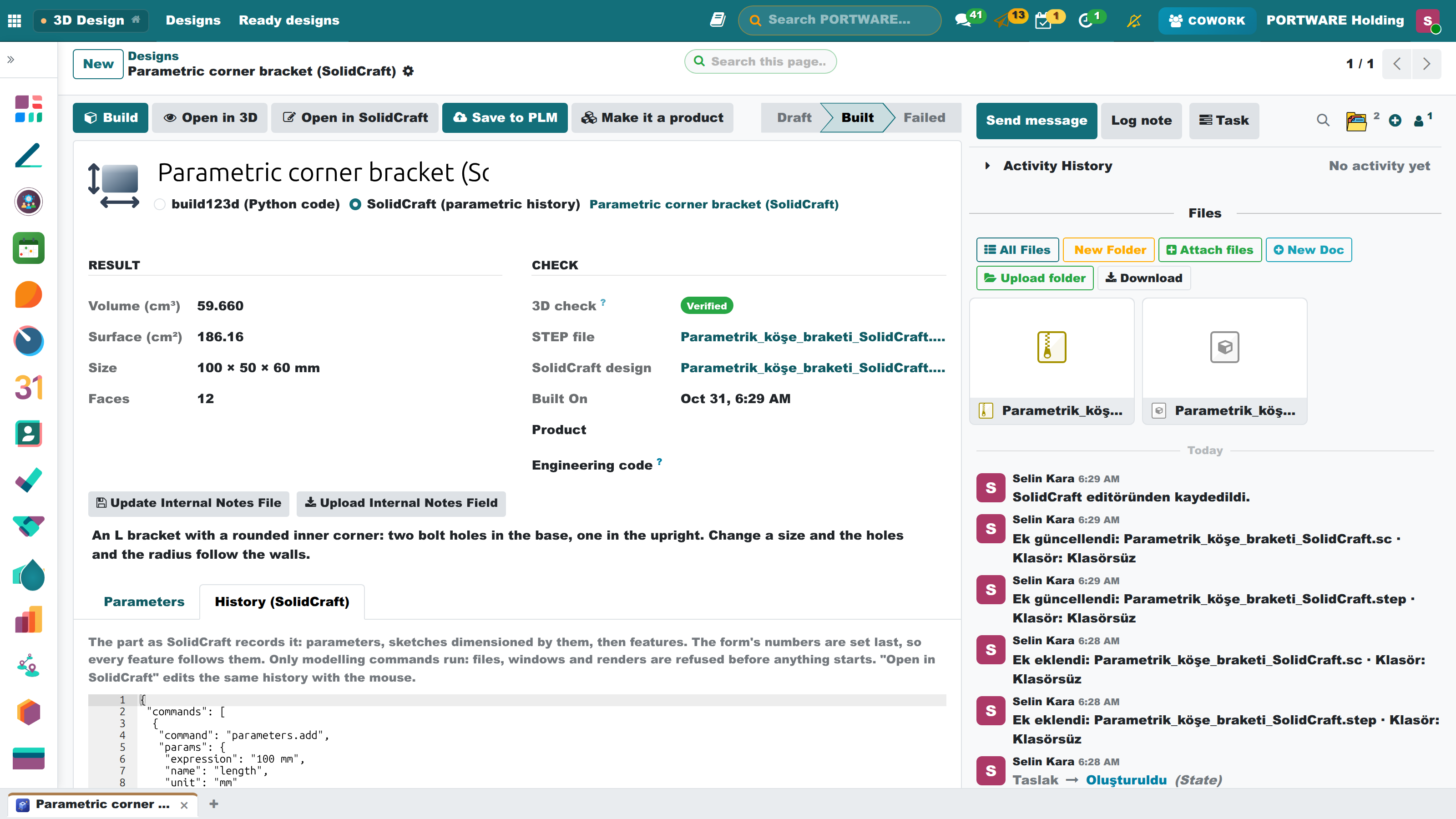
A design has an Engine. build123d describes the part in Python code. SolidCraft (Apache-2.0 / MIT, open source) records it the way a CAD program does: parameters first, then sketches dimensioned by them, then features (extrude, fillet, hole).
The form's numbers are written at the end of that history, so the holes and the radius move with the walls. The ready design Parametric corner bracket (SolidCraft) shows it: base 80 → 120 mm, upright 60 → 90 mm, wall 8 → 10 mm, and the volume goes 51.660 → 98.478 cm³, within ten parts per million of the hand calculation.
Building gives the STEP file every design has, and also the design file (.sc) that keeps the history.
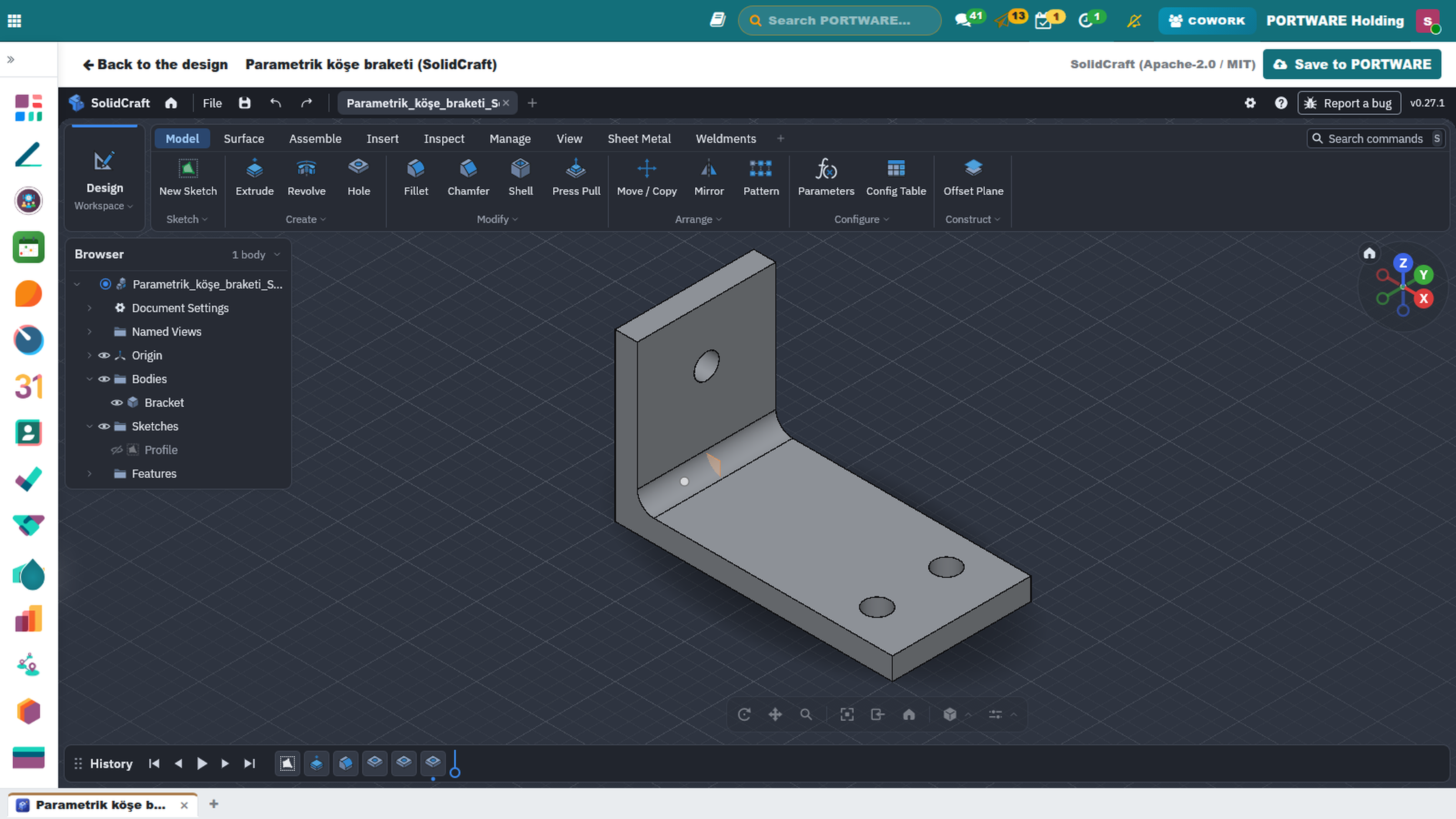
Open in SolidCraft opens the design in SolidCraft's own browser editor, served by the PORTWARE server behind the login. Change sketches, dimensions and features with the mouse, then press Save to PORTWARE: the edited history, parameters, STEP and .sc come back into the design, and the parameter table shows the new values.
A .sc file attached to any record goes to the 3D kernel too: it is turned into STEP first, then checked with both kernels and opened in the CAD viewer like a STEP file.
In plain words, with Cowork
Say "design a 15 mm bracket for the 180 flange motor" and Cowork first reads the design guide: the rules, the building blocks, the ready designs and the company's materials. It then builds a ready design with new numbers or new code; once you accept the card the part is made and its volume, size and link come back.
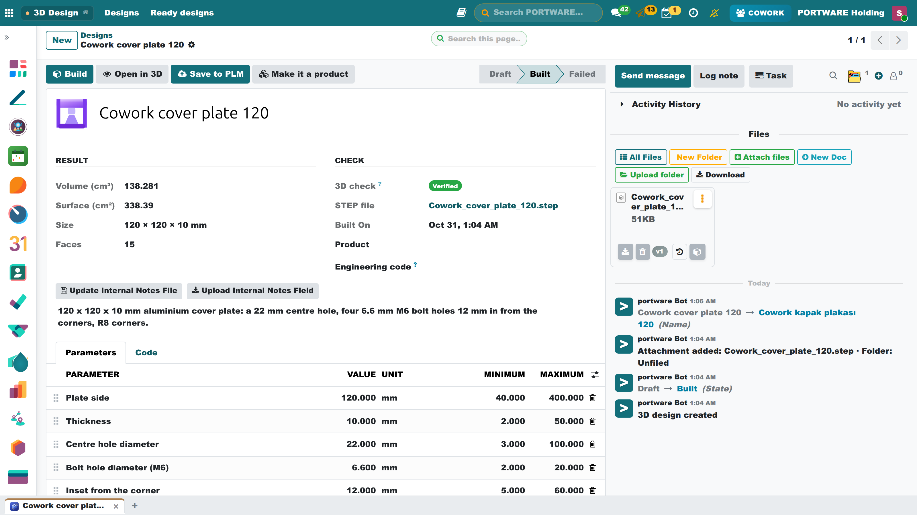
Example (portware.io, Anthropic): "Design a 120 × 120 mm aluminium cover plate, 10 mm thick: a 22 mm hole in the middle, four M6 holes 12 mm in from the corners, R8 corners." Cowork wrote code with six parameters; after the approval the part came out at 138.281 cm³, confirmed by both kernels. The numbers stay on the form: change one and build again. When a build fails Cowork says so; it does not report a part that does not exist.
Safety
The code runs on the server, so it is checked first: only build123d and math may be used; anything reaching files, the network or hidden attributes (open, exec, export…, import…, names starting with _) is refused before it runs. It runs in its own Python environment under a time and memory limit. Writing and building designs is the Designer role; everyone else reads.
A SolidCraft history runs modelling commands only: commands that open or write files, open windows or render are refused before anything runs, and so is any text that looks like a file path. SolidCraft is installed on each server from its own release, never copied into the module.
Then
Open in 3D opens the design in the viewer (exact measurement, render); Make it a product creates a product and attaches the STEP file to it.
Files Open Inside the Application
A 2D/3D file in a chatter, a Cowork link or a card opens in a new tab inside 3D Design; electronics files open inside Electronics Design. The viewer becomes a workbench:
- Ribbon tabs. Design, Inspect, Drawing and PLM; each installed module adds its own commands to them.
- Edit in 3D Design. A STEP, IGES or BREP file opens as a design whose first feature is the imported body, once per file.
- The PLM tab. The document, its parts, revisions, confirm and release, and a change request in one place.
- Add to PLM. A file that is only an attachment becomes a draft PLM document: the company's next DOC number, the part's own number for its drawing, a description from the file name and a new part on request. A taken code or a file already in PLM is refused.
Save to PLM
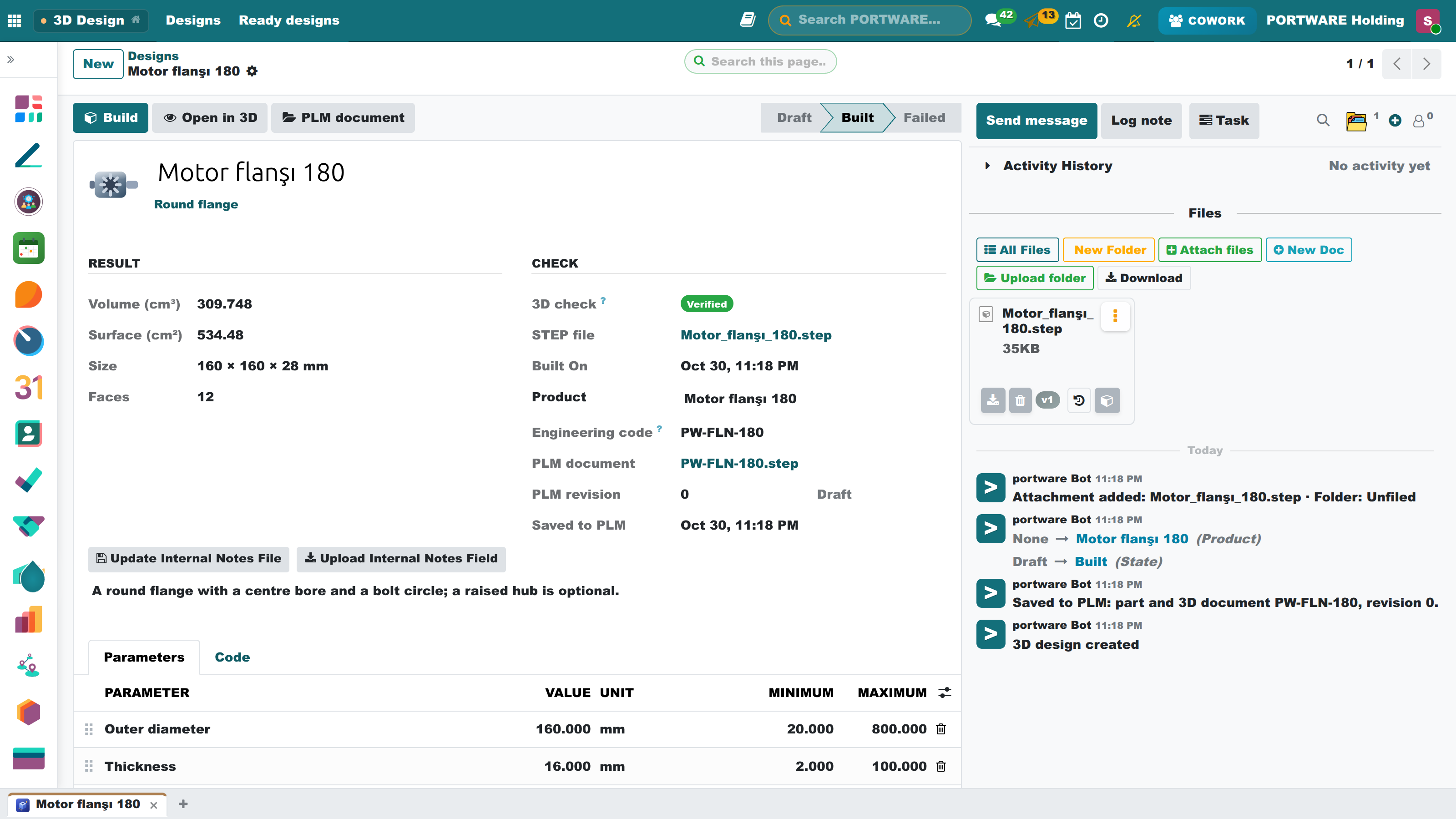
Where PLM is installed, Save to PLM turns the design into a part with an engineering code and its 3D document. The code comes from the form's Engineering code, else the product's, else the next DSN number.
The button comes back when the design changes. A draft document is written again; a confirmed or released one is left alone and changes through a new revision in PLM. A document someone else holds checked out is refused. Every document keeps the code and the numbers that made it: how an older revision was built reads on its 3D design tab.
| Module | What it does | Version |
|---|---|---|
| PORTWARE 3D Design | Design exact parts in a few numbers or in plain words: build123d on OpenCascade, checked by the 3D kernel, ready for the viewer and the product | 19.0.6.8.2 live |
| PORTWARE 3D Design for Cowork | Describe a part in words; Cowork writes the build123d code from what PORTWARE knows, builds it and hands back an exact, checked STEP solid | 19.0.1.7.0 live |
| PORTWARE 3D Design for PLM | A built design becomes a PLM part with its STEP document; every save keeps the code and the numbers that made it, revision by revision | 19.0.1.2.0 live |
| PORTWARE 3D Design: SolidCraft | Parametric CAD with a history: SolidCraft designs built on the server, edited in the browser, checked by the 3D kernel | 19.0.1.0.4 live |